R&S OSP
Instrument Functions
Module Functions
Quick Start Guide 1505.3896.62 - 14
87
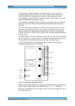
The LED below indicates the status of the interlock (pins 7 and 15). If there is no
connection between these two pins, or if any of the RELAY connectors does not
connect its pins 3 and 4 (bridge at the connector or carrier safety status of the
connected relay), the LED will show a red light indicating an open interlock. The LED
being off indicates that the interlock is closed.
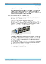
The input ports are available on the upper D-Sub connector IN / OUT. The input port
can be read at any time. Each input is protected with low-pass and diode against
transients.
The output ports are also accessible on the upper D-Sub connector IN / OUT. Each
output channel is designed as a FET driver switching to GND when activated. Each
output is protected with diode against transients which may occur when switching
inductive loads such as relay coils. All output lines can be programmed independently
from each other.
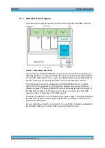
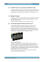
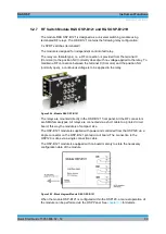
The R&S OSP-B104 module is supplied with power and controlled from the R&S OSP
via one supply and one control connector on the R&S OSP-B104 printed circuit board.
The connection to the R&S OSP is done via those two connection cables.
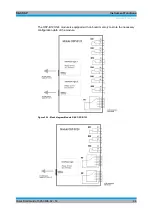
The R&S OSP-B104 module is equipped with an on-board memory to store the
necessary configuration data of the module.
Interface logic
Relay drivers
I
2
C memory
Interface
connector
Output Port
Ch6
To OSP frame
(cable W 5 or 6 or 7)
Ch3
Ch4
Ch5
Ch8
Ch13
Ch9
Ch10
Ch11
Ch12
Ch1
Ch2
Ch15
Ch16
Ch7
Ch14
Ch6
Ch3
Ch4
Ch5
Ch8
Ch13
Ch9
Ch10
Ch1
Ch2
Ch15
Ch16
Ch7
Ch14
+28 V
GND
Ch12
Ch11
RELAY 1
RELAY 2
RELAY 3
IN/OUT
RELAY 4
+28V
OUT1
OUT2
OUT3
OUT4
OUT5
Interlock
PA Intlk Ctl
GND
IN1
IN2
IN3
IN4
PA Intlk Ctl
Interlock
+24V
Status
Interlock
Interlock
Set A
Set B
Set Com
GND
+24V
Status
Interlock
Interlock
Set A
Set B
Set Com
GND
+24V
Status
Interlock
Interlock
Set A
Set B
Set Com
GND
+24V
Status
Interlock
Interlock
Set A
Set B
Set Com
GND
Module OSP-B104
Supply
connector
To OSP frame
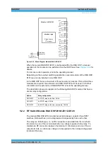
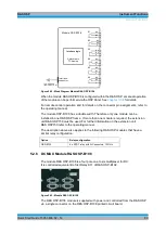
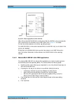
Figure 5-20: Block Diagram Module R&S OSP-B104
When the module R&S OSP-B104 is configured within the R&S OSP, a manual operation
of the module can be performed via the OSP Panel. See
chapter 3.3.9
For remote control operation and for details on the connector pin assignments, refer to
the operating manual.
Summary of Contents for OSP-B011
Page 132: ......

