R&S OSP
Instrument Functions
Module Functions
Quick Start Guide 1505.3896.62 - 14
90
5.2.7 RF Switch Module R&S OSP-B121 and R&S OSP-B121H
The module R&S OSP-B121 is designed as a universal switching module using
terminated RF relays. The OSP-B121 contains the following relay configuration:
3 x SPDT switches (terminated)
The module is designed for independent control of all relay.
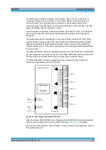
The relay is a failsafe type; i.e. a RF connection is provided from the terminal C
(Common) to the position NC (normally closed) with no voltage applied to the relay. To
maintain a RF connection between the terminal C (Common) and the position NO
(normally open), a continuous voltage is to be applied to the relay.
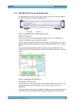
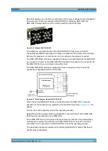
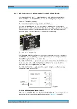
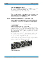
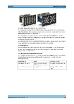
Figure 5-24: Module R&S OSP-B121
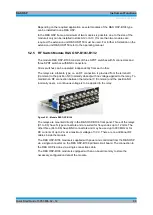
The relays are mounted directly in the OSP-B121 front panel. All the RF connectors
are SMA female types. All relays are connected via a short cable to a printed circuit
board; this way the module is of compact size.
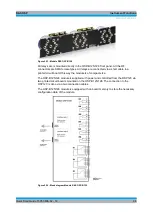
The OSP-B121 module is supplied with power and controlled from the OSP120 via a
single connector on the OSP-B121 printed circuit board. The connection to the
OSP120 is done via a single connection cable.
The OSP-B121 module is equipped with on board memory to store the necessary
configuration data of the module.
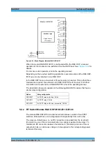
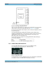
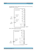
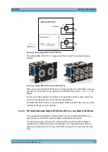
Figure 5-25: Block diagram Module R&S OSP-B121
When the module OSP-B121 is configured within the OSP120, a manual operation of
the module can be performed via the OSP Panel. See
chapter 3.3
Summary of Contents for OSP-B011
Page 132: ......


