Getting Started
R&S
®
OSP
26
User Manual 1178.7100.02 ─ 05
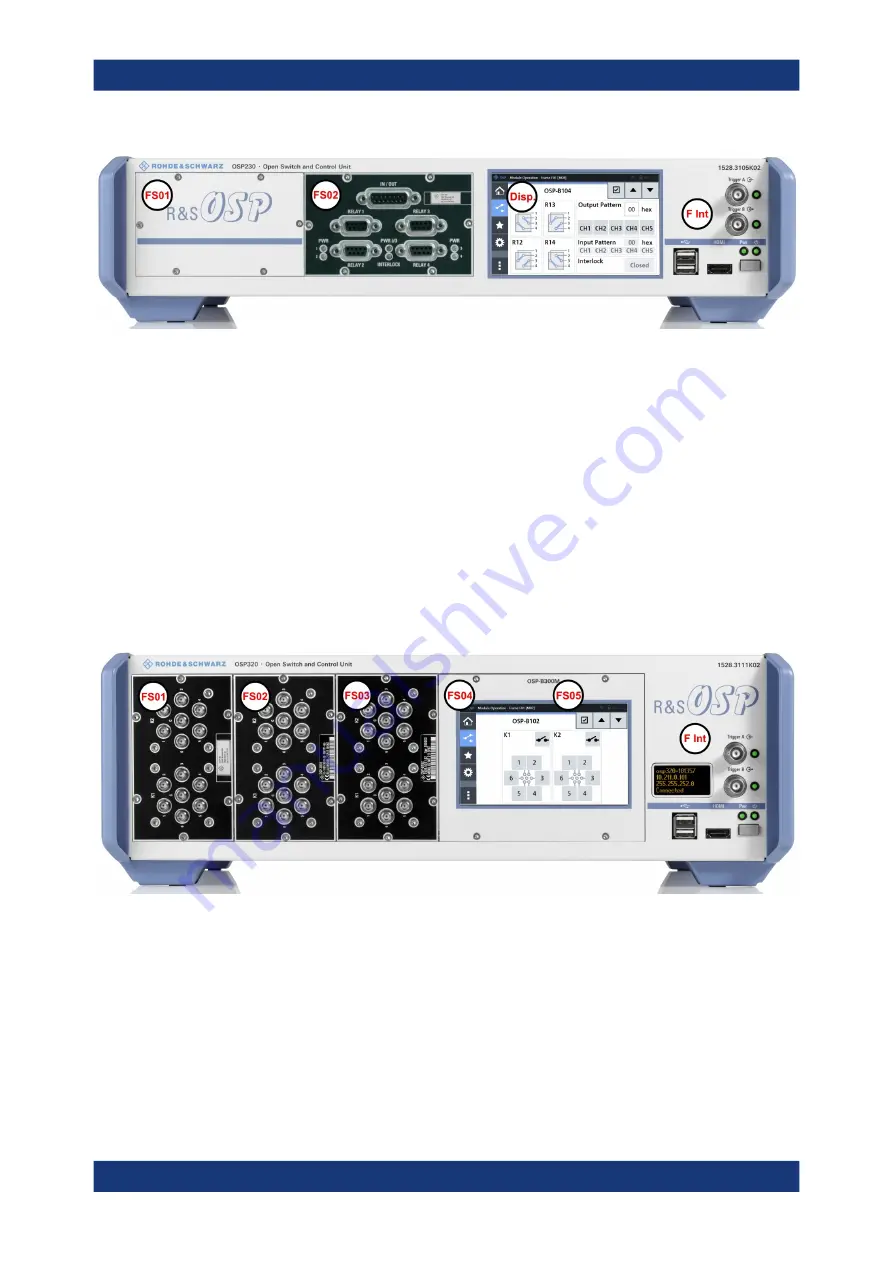
Figure 2-4: Front view of the R&S
OSP230 (2HU)
FS01 = Front slot 01, here with a blind plate
FS02 = Front slot 02, here with a 1-slot switch module
Disp. = Integrated touchscreen display (and no front slot 03)
F Int = Front interfaces, see
2.2.1.3
Front Panel of the R&S
OSP320
The R&S
OSP320 is higher than all other switch units from Rohde
&
Schwarz. With its
3 height units (3HU), it enables a more dense fitting of 1-slot switch modules within the
same instrument width. Hence, its front panel features 5 module slots, along with a
power switch, a status display and various connectors.
2 of the 5 front slots (labeled FS04 and FS05 in
ted optional touchscreen display module R&S
OSP-B300M:
Figure 2-5: Front view of the R&S
OSP320 (3HU)
FS01 to FS03 = Front slots 01 to 03, here each with a 1-slot switch module
FS04 + FS05 = Front slot 04 and 05, here with mounted touchscreen display module
F Int
= Front interfaces and status display (OLED, 128 x 64 pixels), see
optional. It can only be factory-mounted in the R&S
OSP320 with 3 height units (3HU)
in position FS04 + FS05.
You cannot insert any modules into the R&S
OSP320 that are designed as 2-slot or 3-
slot modules for a switch unit with 2 height units (2HU, see above).
Instrument Tour


