Getting Started
R&S
®
OSP
35
User Manual 1178.7100.02 ─ 05
●
Additional information
:
–
"Trigger"
–
"Locked"
, no additional information is dis-
played. Also, if both a connection message and a device message are shown
already, additional information (which has lower relevance) is skipped due to a lack
of space.
●
Connection state
information:
If none of the above is valid, the 4
th
line of the status display shows one of the fol-
lowing states of the switch unit:
–
"Auto DHCP" (which also implies "Single" state)
–
"Static IP" (which also implies "Single" state)
–
"Disconnected"
During shutdown, the status display displays "Terminating...".
You cannot operate the switch units R&S
OSP220
‒
and the R&S
OSP320 without dis-
play module R&S
OSP-B300M
‒
by their status displays. To operate these switch units
without the graphical user interface of a built-in full touchscreen display, use one of the
following alternatives:
●
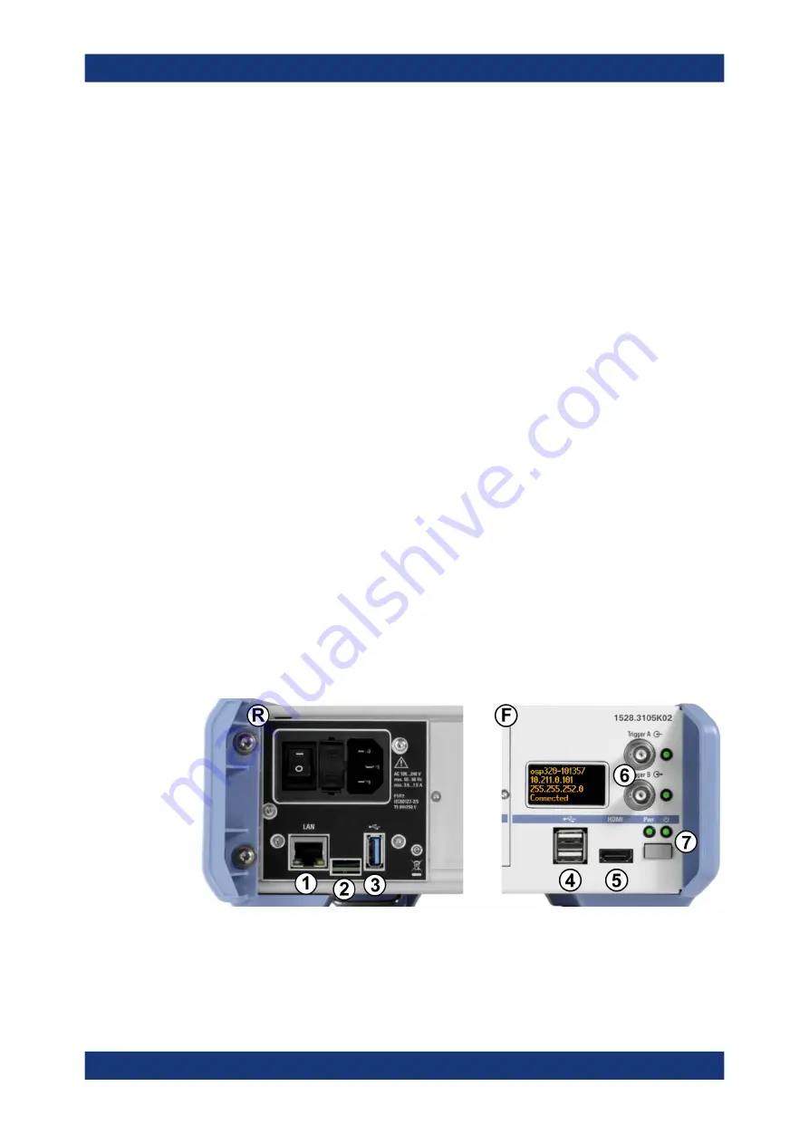
, connect an external monitor to the HDMI
connector on the unit's front panel (labeled 5 in
mouse and keyboard to the USB connectors, labeled (4).
●
Use the switch unit as a secondary device in
Chapter 4.4, "Operation in Interconnection Mode"
●
Connect the switch unit to a local area network (LAN) by the RJ45 connector on
the unit's rear panel. The connector is labeled (1) in
address from the status display and proceed as described in
Chapter 2.3.1.3, "Remote Operation
Figure 2-16: Connectors and functional elements on the switch unit's rear and front panel
Trying Out the Switch Unit


