Getting Started
R&S
®
OSP
36
User Manual 1178.7100.02 ─ 05
R = Rear interfaces (where the R&S
OSP320 has an additional trigger port, see
)
F = Front interfaces (where the R&S
OSP230 has no OLED status display, see
I/0 = Main power switch with fuse holder and power connector
1 = LAN connector (RJ45)
2 = Slot for the micro SD card that holds the switch unit's operating system
3 = USB 3.1 connector
4 = Two USB 2.0 connectors (for external mouse and keyboard)
5 = HDMI connector (for an external monitor)
6 = Two BNC trigger input connectors (A and B, with two trigger status LEDs), see below
7 = Front power switch with [Pwr] and LAN status LEDs
If you connect an external monitor to the
HDMI
connector (5), use a monitor that is
compatible with this port’s DVI signal. This signal is configured for the touchscreen's
resolution of 800 x 480 pixels. Incompatible monitors cannot display the graphical user
interface.
With the
trigger
connectors (6), the R&S
OSP is prepared for external triggering,
which requires the
R&S
OSP-K100
. Firmware versions below
version
2.00
do not support this trigger option.
Note that the rear interface panel of the R&S
OSP320 has an additional D-Sub
9 trig-
ger connector, as shown in
.
In any of these configurations, you can operate a switch unit by its user interface:
either on an external monitor or in a web browser (we recommend using
Chrome
as
browser). The same holds true for the R&S
OSP230 and R&S
OSP320 with integrated
display module R&S
OSP-B300M, which allow touchscreen operation.
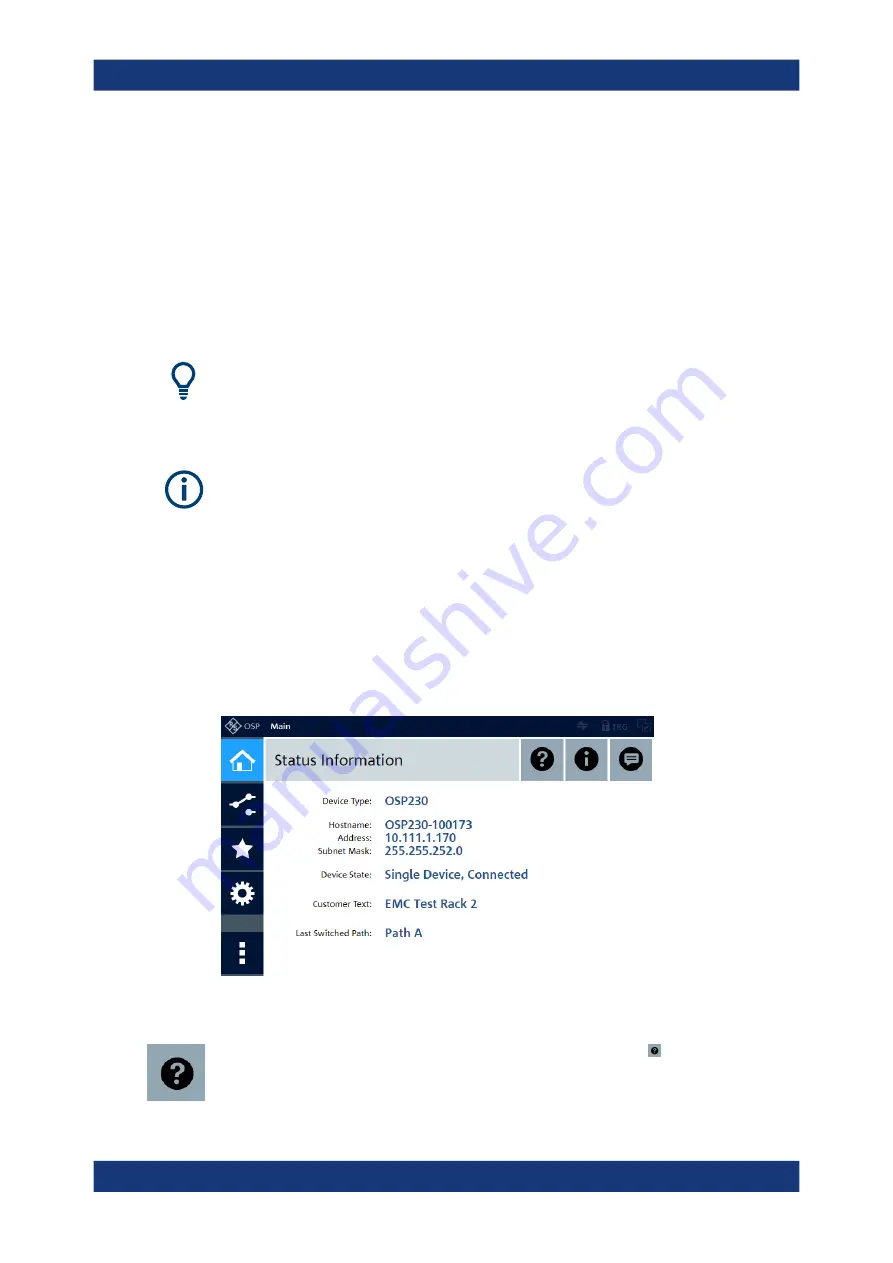
Using any of these options, you get access to the graphical user interface (GUI):
Figure 2-17: Main menu of the graphical user interface ("WebGUI"), here in the recommended
Chrome browser
In the "Main" menu of the user interface, clicking the "Help" icon in the top right area
opens an overview of the available functions:
Trying Out the Switch Unit


