Modules
R&S
®
OSP
67
User Manual 1178.7100.02 ─ 05
The relay type is multi-stable (or "latching"). Hence, with no voltage applied, a relay
remains in its current position. It also remains in its current position, if the voltage is
maintained after switching is accomplished.
To change the connection, the controller must send a voltage pulse to the appropriate
switch coil in the relay. After that, no energy is consumed by this relay type.
You can configure two different
to determine, how
the latching relay behaves after booting the switch unit.
The relay is mounted directly into the module's panel and soldered to the module's
printed board, to avoid relay cabling and allow a compact module size.
The switch unit provides power supply and control via a single module bus cable to a
module bus connector on the module's printed board. The module's on-board memory
stores its configuration data.
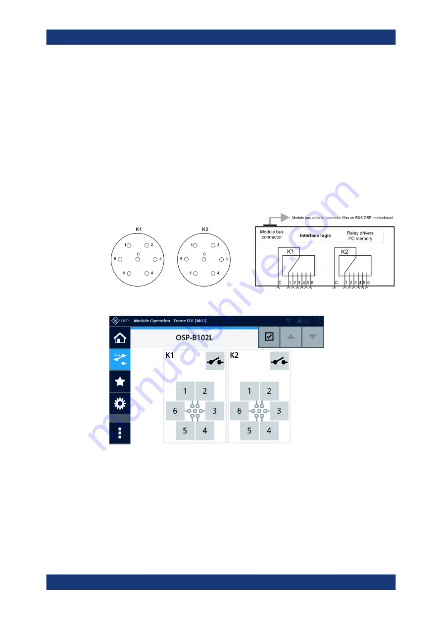
Figure 3-20: Pinout and block diagram of RF switch module R&S
OSP-B102L
Figure 3-21: Representation of the module on the control screen
For operation, see
For remote control, refer to the chapters
R&S
OSP-B102L RF Switch Module


