Modules
R&S
®
OSP
69
User Manual 1178.7100.02 ─ 05
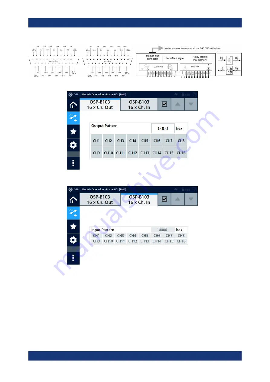
Figure 3-23: Pinout and block diagram of RF switch module R&S
OSP-B103
Figure 3-24: Representation of the module's output channels on the control screen
Figure 3-25: Representation of the module's input channels on the control screen
For operation, see
For remote control, refer to the chapters
for reading the 16 input channels.
R&S
OSP-B103 Digital I/O Module


