Modules
R&S
®
OSP
73
User Manual 1178.7100.02 ─ 05
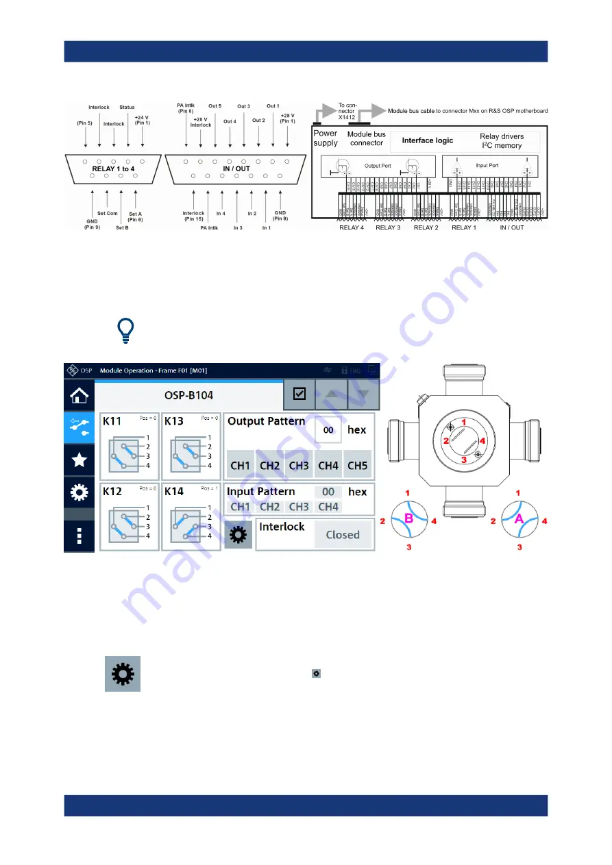
Figure 3-27: Pinout and block diagram of RF switch module R&S
OSP-B104
Left
= 9-pin [RELAY n] connectors (4x), see also
Center = 15-pin [INTERLOCK] I/O connector (1x)
Right = Block diagram
For connection details, see
Chapter 6.2.1, "Controlling External Power Relays with
Figure 3-28: Representation of the module on the control screen, the external relays are K11 to K14
Right = Schematic of an external Spinner relay with port labels (red) and position indicator (center dial)
B
= Relay not activated ("Set B" pulse), terminals 1 + 4 and 2 + 3 are connected
A
= Relay activated ("Set A" pulse), terminals 1 + 2 and 3 + 4 are connected
You can read the interlock state of the R&S
OSP-B104 (shown on the lower right in
To set individual delay times for each external transfer relay K11 to K14, click the but-
ton "Configure Relay Delay Times" in the control screen shown in
following dialog opens:
R&S
OSP-B104 Digital I/O Module (EMS)


