Functions
R&S
®
OSP
174
User Manual 1178.7100.02 ─ 05
...............................................................................176
.......................................................................... 179
.......................................................................... 180
Delete Virtual Configuration File
................................................................... 181
Lock Mode
Access: "Module Operation" > "Context Menu" > "Lock Mode"
Freezes the state of your setup by locking the switching of relays and output channels
and limiting the available settings.
To enable the lock mode, click the "Lock Mode" button in the user interface (touch-
screen or
) or use the RC command
An enabled lock mode has the following effects:
●
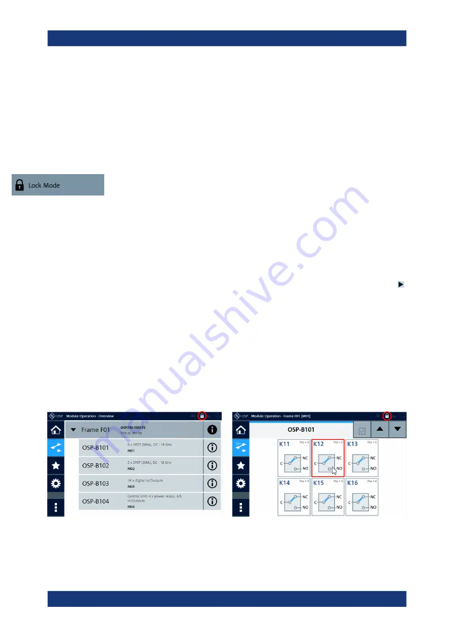
The lock mode indicator icon is highlighted (see red circles in
●
You cannot change the state of relays and output channels. If you try to switch one
of them, a red rectangle (as in
) reminds you of the locked state.
●
You cannot switch paths. If you try to switch one of them, the
button
is highlighted in red.
●
For primary and secondary switch units, the locking applies as follows:
–
In the primary switch unit, the lock mode prevents switching via the user inter-
face and via
–
In secondary switch units, where switching via the user interface is locked any-
way due to the interconnection mode, the lock mode also prevents switching
via remote operation
●
The
●
The
is disabled (see
)
●
You cannot change the
●
However, you can change the
configuration, and the lock mode
does not prevent other commands (see also
).
Figure 5-21: Module Operation dialog of a switch unit and of one module in lock mode
Red circles
= This icon is the lock mode indicator
Red rectangle = Reminds you of the locked state, when you click a switch
Module Operation


