Application Examples
R&S
®
OSP
231
User Manual 1178.7100.02 ─ 05
6.1.3
Output Ports of R&S
OSP-B103
Each output channel is designed as a MOS-FET (open drain) that leaves the channel's
pin on high impedance in the inactive state. When activated, the FET switches the pin
to internal ground. Each output is protected by two TVS diodes against transient distur-
bances, which can occur when switching inductive loads such as relay coils.
Output current limits
●
The output ports can draw a maximum of 200
mA, each.
●
The R&S
OSP can supply a maximum current of 600
mA to all OUT ports together.
●
The maximum total current for all slots in the switch unit is 10
A.
6.2
Applications of Module R&S
OSP-B104
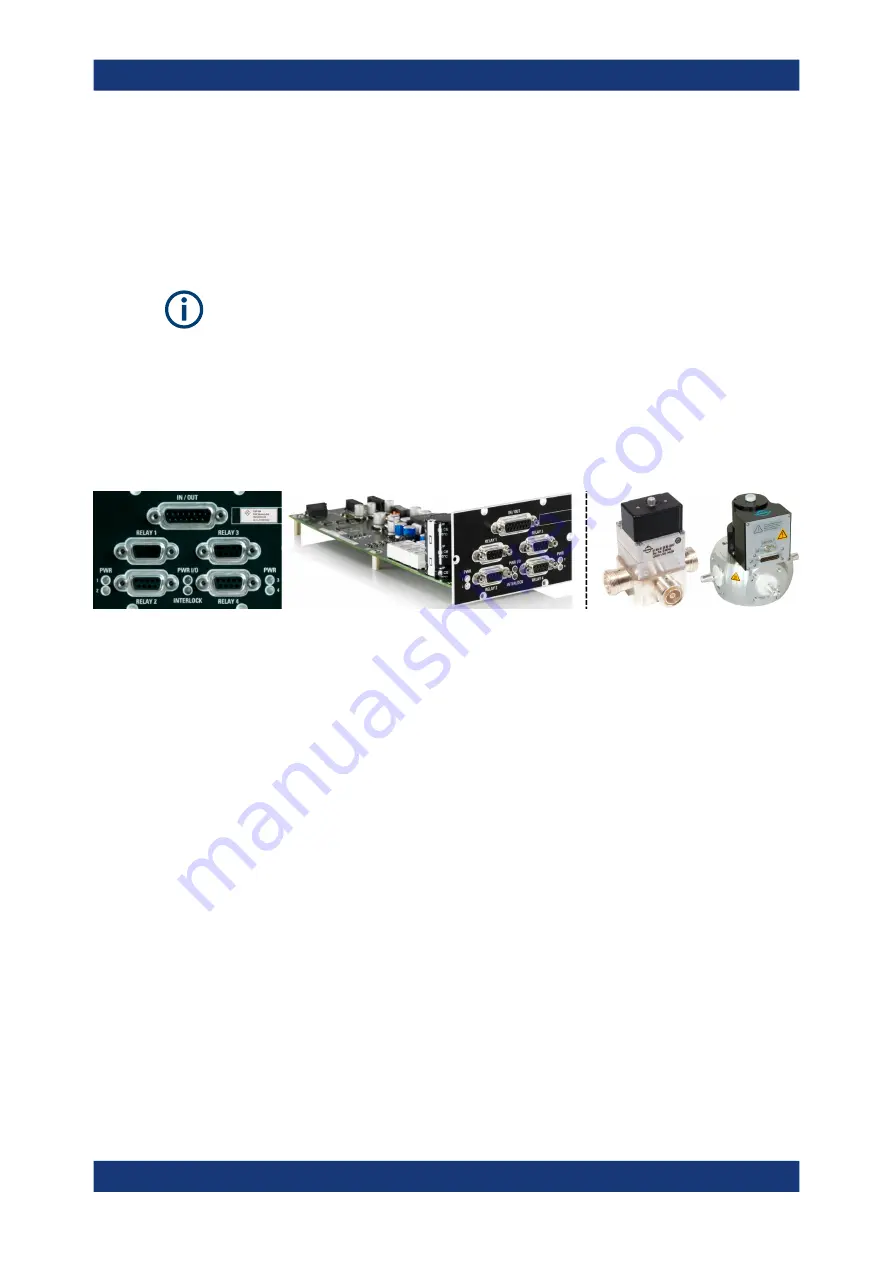
Figure 6-4: R&S
OSP-B104 (detail on the right: 3rd-party Spinner relays)
This chapter describes using the
OSP-B104 Digital I/O Module (EMS)
input/output ports for the following applications in EMS systems:
●
Controlling up to 4 high-power RF relays
●
Monitoring an interlock loop that uses door switches and high-power relays
●
Relaying the interlock status to any connected power amplifier
●
Ancillary 4 input channels and 5 output channels for arbitrary use
Controlling External Power Relays with R&S
......................................231
.............................................................233
.............................................................................. 234
........................................................................... 234
6.2.1
Controlling External Power Relays with R&S
OSP-B104
The module R&S
OSP-B104 has four connectors to control external power relays. The
following relay models from Spinner GmbH are supported by this module:
Applications of Module R&S
OSP-B104


