Getting Started
R&S
®
OSP
46
User Manual 1178.7100.02 ─ 05
1 = The module that you mount (here: on the rear side of an R&S
OSP220 or R&S
OSP230)
2 = Rear slot RS02, opened for mounting the module
3 = Rear slots RS01 and RS03, covered by blank plates
4 = Six torx
8 screws
5 = Module bus cable (flat-ribbon cable), held by its clamp
6 = Removable panel struts, fixed by 2 Torx
8 screws
12. Carefully insert the module into the open slot.
Special issues with the 3-HU switch unit R&S
OSP320:
● If you insert a module into the switch unit R&S
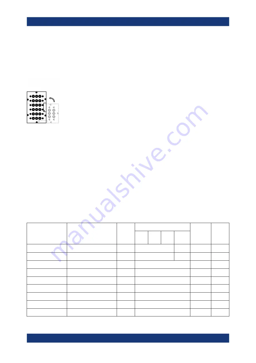
OSP320, insert the module rota-
ted counterclockwise by 90°. Hence, if you face the panel of the module that
you mount, rotate it to the left.
● Note that you can mount only one-slot modules (panel size 65.5
mm x
107.6
mm) into the R&S
OSP320.
13. Fix the inserted module with the six original screws (or more screws, if you mount a
larger module).
14. Reconnect the switch unit (see
).
15. Switch on the switch unit.
During start-up, all modules automatically register in the switch unit. You do not
have to interact with this process. No manual registration or testing is required.
The switch unit and its mounted modules are ready for use.
2.4.1
Module Integration Overview
The following table shows, which
occupy 1, 2 or 3 slots, and which modules
can be mounted into which switch unit. It also shows, if you must open the switch unit
for mounting a module, and how many module bus cables each module requires.
Table 2-4: Module integration parameters
Module name
Order no.
(number
of slots)
Suited for integration into
Requires
opening
the switch
unit
Number
of mod-
ule bus
cables
1
OSP
220
OSP
230
OSP
320
OSP-
B200S2
1505.4763.02
1
yes (+ RF cables)
no
yes
2
0
1505.4770.02
1
yes (+ RF cables)
no
yes
2
0
1528.1625.11 / .12 / .13
1
yes
no
1
1528.1625.21 / .22 / .23
1
yes
no
1
1528.1625.41 / .42 / .43
1
yes
no
1
1528.1625.51 / .52 / .53
1
yes
no
1
1505.5101.02
1
yes
no
1
1505.5101.52
1
yes
no
1
1505.5201.02
1
yes
no
1
Mounting a Module


