Modules
R&S
®
OSP
70
User Manual 1178.7100.02 ─ 05
For application examples, see also
Chapter 6.1, "Applications of Module R&S
3.11
R&S
OSP-B104 Digital I/O Module (EMS)
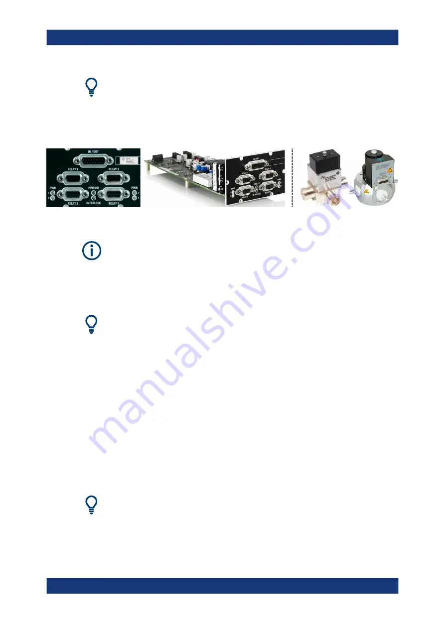
Figure 3-26: R&S
OSP-B104 (detail on the right: 3rd-party Spinner relays)
If this module is not factory-mounted, contact Rohde
&
Schwarz
for mounting it.
The digital input/output one-slot
OSP-B104 (order no. 1505.5401.02) is
designed for special applications in electromagnetic susceptibility (EMS) measure-
ments.
See also
Chapter 6.2, "Applications of Module R&S
Its
4 [RELAY] ports
are female 9-pin D-Sub connectors that allow controlling up to 4 of
the following external power-transfer relays from a
●
(replacing BN 512670),
Rohde
&
Schwarz order no. 0546.2300.00. The type is DPDT, latching, DC to
5
GHz, with female RF connectors of type 7/16 and impulse solenoid drive. RF
input power up to 2
kW @ 100
MHz (details see
).
●
(replacing BN 640075), Rohde
&
Schwarz order
no. 2108.9517.00. The type is DPDT, latching, DC to 2
GHz, with female RF flange
connectors of type 1 5/8” EIA and motor drive. RF input power up to 20
kW @
100
MHz.
●
, Rohde
&
Schwarz order no. 2108.9500.00. The
type is DPDT, latching, DC to 3.5
GHz, with female RF flange connectors of type
7/8” EIA and motor drive. RF input power up to 7.5
kW @ 100
MHz.
For connecting the Spinner relays, see
Chapter 6.2.1, "Controlling External Power
You can use other transfer relays, if they are compatible with the output of the
R&S
OSP-B104 control lines. For specifications, refer to the R&S
OSP data sheet.
R&S
OSP-B104 Digital I/O Module (EMS)


