Chapter 3
Installation
5300.9677.72
- 3.8 -
EN-4
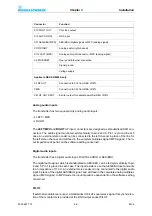
Analog audio inputs
The transmitter has two equal-priority analog audio inputs:
LEFT / MPX
RIGHT
The
LEFT/MPX
and
RIGHT
AF input connectors are designed as standardized XLR con-
nectors. The audio signal can be fed symmetrically to pin 2 and 3. Pin 1 is ground in each
case. An external stereo coder can be connected to the left channel in place of the line for
the left stereo channel, and will feed in the complete multiplex signal (MPX signal). The in-
put impedance depends on the software setting concerned.
Digital audio inputs
The transmitter has a digital audio input - DIGITAL AUDIO or AES/EBU.
The digital audio signal, which is standardized to AES/EBU, can be fed symmetrically to pin
2 and 3. Pin 1 is ground in each case. The input resistance on the AES/EBU input amounts
to an impedance of 110
Ω
. An external stereo coder can be connected to the digital audio
input in place of the digital AES/EBU signal, and will feed in the complete analog multiplex
signal (MPX signal). In MPX mode the input impedance dependent on the software setting
concerned.
PILOT
If external modulators are used, a standardized 19 kHz squarewave signal for synchroniza-
tion of the modulators is provided at the BNC output socket PILOT.
X13 PILOT OUT
Pilot tone output
X12 AUX1 (RDS)
RDS input
X21 AES/EBU (MPX)
AES/EBU (digital signal) or MPX (analog signal)
X11R RIGHT
Analog audio (right channel)
X11L LEFT (MPX)
Analog audio (left channel) or MPX (analog signal)
X6 ETHERNET
Rear panel Ethernet connection
Signal ground
Voltage supply
Applies to R&S SR8250A only
X2 RF OUT
Connection to X10 from R&S VU813
X22B
Connection to X22 from R&S VU813
X61 RF OUT SPLIT
Exciter output for separate amplifier R&S VU813
Connector
Function
Summary of Contents for SR8000 Series
Page 3: ......
Page 7: ...5300 9677 72 0 4 EN 4 ...
Page 8: ...Broadcasting Division 5300 9677 72 1 1 EN 4 Printed in Germany CHAPTER 1 SAFETY ...
Page 9: ......
Page 21: ...5300 9677 72 1 14 EN 4 Chapter1 Safety ...
Page 22: ...Broadcasting Division 5300 9677 72 2 1 EN 4 Printed in Germany CHAPTER 2 DESIGN AND FUNCTION ...
Page 23: ......
Page 27: ...Chapter2 Design and Function 5300 9677 72 2 6 EN 4 Fig 4 R S SR8000 block diagram ...
Page 49: ...Chapter2 Design and Function 5300 9677 72 2 28 EN 4 ...
Page 50: ...Broadcasting Division 5300 9677 72 3 1 EN 4 Printed in Germany CHAPTER 3 INSTALLATION ...
Page 51: ......
Page 63: ......
Page 88: ...Broadcasting Division 5300 9677 71 5 1 EN 4 Printed in Germany CHAPTER 5 OPERATION ...
Page 89: ......
Page 157: ...Chapter5 Operation 5300 9677 71 5 70 EN 4 ...
Page 158: ...Broadcasting Division 5300 9677 72 6 1 EN 4 Printed in Germany CHAPTER 6 MAINTENANCE ...
Page 159: ......
Page 166: ...Broadcasting Division 5300 9677 72 7 1 EN 4 Printed in Germany CHAPTER 7 TROUBLESHOOTING ...
Page 167: ......
Page 168: ...Chapter7 Troubleshooting 5300 9677 72 7 3 EN 4 CONTENTS 1 Information 4 ...
Page 170: ...Broadcasting Division 5300 9677 72 8 1 EN 4 Printed in Germany CHAPTER 8 SERVICE ...
Page 171: ......
Page 184: ...Broadcasting Division 5300 9677 72 9 1 EN 4 Printed in Germany CHAPTER 9 APPENDIX ...
Page 185: ......
Page 197: ...Chapter9 Appendix 5300 9677 72 9 14 EN 4 ...
Page 198: ...Broadcasting Division 5300 9677 72 A 1 EN 4 Printed in Germany WIRING DIAGRAMS ...
Page 199: ......


