background image

Instrucciones de seguridad elementales 

1171.0000.42 - 07 

Page 10 

1.  Si no se convino de otra manera, es para los productos Rohde & Schwarz válido lo que sigue:  

como posición de funcionamiento se define por principio la posición con el suelo de la caja para 
abajo, modo de protección IP 2X, uso solamente en estancias interiores, utilización hasta 2000 m 
sobre el nivel del mar, transporte hasta 4500 m sobre el nivel del mar. Se aplicará una tolerancia de 

±

10 % sobre el voltaje nominal y de 

±

5 % sobre la frecuencia nominal. Categoría de sobrecarga 

eléctrica 2, índice de suciedad 2.  

2.  No sitúe el producto encima de superficies, vehículos, estantes o mesas, que por sus características 

de peso o de estabilidad no sean aptos para él. Siga siempre las instrucciones de instalación del 
fabricante cuando instale y asegure el producto en objetos o estructuras (p. ej. paredes y estantes). Si 
se realiza la instalación de modo distinto al indicado en la documentación del producto, se pueden 
causar lesiones o, en determinadas circunstancias, incluso la muerte. 

3.  No ponga el producto sobre aparatos que generen calor (p. ej. radiadores o calefactores). La 

temperatura ambiente no debe superar la temperatura máxima especificada en la documentación del 
producto o en la hoja de datos. En caso de sobrecalentamiento del producto, pueden producirse 
choques eléctricos, incendios y/o lesiones graves con posible consecuencia de muerte. 

Seguridad eléctrica 

Si no se siguen (o se siguen de modo insuficiente) las indicaciones del fabricante en cuanto a seguridad 
eléctrica, pueden producirse choques eléctricos, incendios y/o lesiones graves con posible consecuencia 
de muerte. 


1.  Antes de la puesta en marcha del producto se deberá comprobar siempre que la tensión 

preseleccionada en el producto coincida con la de la red de alimentación eléctrica. Si es necesario 
modificar el ajuste de tensión, también se deberán cambiar en caso dado los fusibles 
correspondientes del producto.  

2.  Los productos de la clase de protección I con alimentación móvil y enchufe individual solamente 

podrán enchufarse a tomas de corriente con contacto de seguridad y con conductor de protección 
conectado. 

3.  Queda prohibida la interrupción intencionada del conductor de protección, tanto en la toma de 

corriente como en el mismo producto. La interrupción puede tener como consecuencia el riesgo de 
que el producto sea fuente de choques eléctricos. Si se utilizan cables alargadores o regletas de 
enchufe, deberá garantizarse la realización de un examen regular de los mismos en cuanto a su 
estado técnico de seguridad. 

4.  Si el producto no está equipado con un interruptor para desconectarlo de la red, o bien si el 

interruptor existente no resulta apropiado para la desconexión de la red, el enchufe del cable de 
conexión se deberá considerar como un dispositivo de desconexión.  
El dispositivo de desconexión se debe poder alcanzar fácilmente y debe estar siempre bien accesible. 
Si, p. ej., el enchufe de conexión a la red es el dispositivo de desconexión, la longitud del cable de 
conexión no debe superar 3 m).  
Los interruptores selectores o electrónicos no son aptos para el corte de la red eléctrica. Si se 
integran productos sin interruptor en bastidores o instalaciones, se deberá colocar el interruptor en el 
nivel de la instalación. 

5.  No utilice nunca el producto si está dañado el cable de conexión a red. Compruebe regularmente el 

correcto estado de los cables de conexión a red. Asegúrese, mediante las medidas de protección y 
de instalación adecuadas, de que el cable de conexión a red no pueda ser dañado o de que nadie 
pueda ser dañado por él, p. ej. al tropezar o por un choque eléctrico.  

Summary of Contents for TSME-Z3

Page 1: ...R S TSME Z3 Backpack System for TSME Drive Test Scanner Getting Started Getting Started C9 2 1519 0994 02 02 Test Measurement...

Page 2: ...s not binding R S is a registered trademark of Rohde Schwarz GmbH Co KG CDMA2000 is a registered trademark of the Telecommunications Industry Association TIA USA WiMAX Forum is a registered trademark...

Page 3: ...the product The product is used for its designated purpose if it is used in accordance with its product documentation and within its performance limits see data sheet documentation the following safe...

Page 4: ...dangers Indicates a hazardous situation which if not avoided will result in death or serious injury Indicates a hazardous situation which if not avoided could result in death or serious injury Indicat...

Page 5: ...ot observed either at all or to the extent necessary electric shock fire and or serious personal injury or death may occur 1 Prior to switching on the product always ensure that the nominal voltage se...

Page 6: ...be fuse protected in such a way that anyone who has access to the product as well as the product itself is adequately protected from injury or damage 14 Use suitable overvoltage protection to ensure...

Page 7: ...masks and protective clothing must be worn 7 Laser products are given warning labels that are standardized according to their laser class Lasers can cause biological harm due to the properties of the...

Page 8: ...n permitted 5 If a cell develops a leak the fluid must not be allowed to come into contact with the skin or eyes If contact occurs wash the affected area with plenty of water and seek medical aid 6 Im...

Page 9: ...s substances or fuels can cause health problems and lead to environmental damage For additional information about environmental protection visit the Rohde Schwarz website Instrucciones de seguridad el...

Page 10: ...el uso del producto Deber n tenerse en cuenta todas las dem s informaciones de seguridad como p ej las referentes a la protecci n de personas que encontrar n en el cap tulo correspondiente de la docu...

Page 11: ...l producto se emplea de forma sin nima el t rmino CUIDADO Las palabras de se al corresponden a la definici n habitual para aplicaciones civiles en el rea econ mica europea Pueden existir definiciones...

Page 12: ...la tensi n preseleccionada en el producto coincida con la de la red de alimentaci n el ctrica Si es necesario modificar el ajuste de tensi n tambi n se deber n cambiar en caso dado los fusibles corre...

Page 13: ...efectuadas por un electricista especializado 13 En el caso de dispositivos fijos que no est n provistos de fusibles interruptor autom tico ni otros mecanismos de seguridad similares el circuito de ali...

Page 14: ...empresario operador tiene la obligaci n de evaluar y se alizar las reas de trabajo en las que exista un riesgo elevado de exposici n a radiaciones 6 Tenga en cuenta que en caso de incendio pueden desp...

Page 15: ...r ni fuego Debe evitarse el almacenamiento a la luz directa del sol Las celdas y bater as deben mantenerse limpias y secas Limpiar las conexiones sucias con un pa o seco y limpio 3 Las celdas o bater...

Page 16: ...vos el ctricos usados no se deben desechar con los residuos dom sticos sin clasificar sino que deben ser recogidos por separado Rohde Schwarz GmbH Co KG ha elaborado un concepto de eliminaci n de resi...

Page 17: ...ed for exam ple according to the ISO9001 and ISO14001 management systems Environmental commitment Energy efficient products Continuous improvement in environmental sustainability ISO14001 certified en...

Page 18: ...ument up to date and to be informed about new application notes related to your instrument please send an e mail to the Customer Support Center stating your instrument and your wish We will take care...

Page 19: ...Z3 backpack provides such a solution which allows for indoor measurements of coverage and interfer ence in GSM WCDMA LTE CDMA2000 EVDO TD SCDMA WiMAX and TETRA networks In addition to scanner measure...

Page 20: ...ner and Mobile Device Configuration on page 8 Framework to mount up to two optional recharcheable batteries acces sory see chapter 2 3 Power Supply on page 6 Gigabit Ethernet switch 4 DL ports for R S...

Page 21: ...lead through the side wall for external operation Fig 2 1 Fully equipped R S TSME Z3 backpack 2 2 System Unit The system unit contains the following connectors and interface elements Fig 2 2 System un...

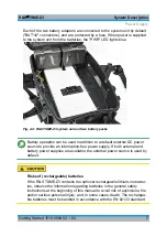
Page 22: ...nal DC power source typically a car bat tery No batteries are required inside the backpack A DC power supply cable with a cigarette lighter plug is provided with the R S TSME Z3 The external DC power...

Page 23: ...t external DC power source to provide an interruption free power supply If both external and battery power supplies are available the external power source is used by default Risks of rechargeable bat...

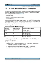
Page 24: ...one position one TSME Z3M1 mounting kit for one mobile device is required The following configurations are possible Table 2 1 Possible R S TSME Z3 configurations Number of R S TSMEs Max number of mobi...

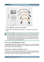
Page 25: ...gured in the factory according to the user s specifications at an extra charge Please contact your local Rohde Schwarz sales office Connectors for R S TSME Ethernet switch The gigabit Ethernet switch...

Page 26: ...ackpack Ensure that all fan openings on both sides of the backpack are unobstructed and the airflow perforations are unimpeded Setting up the System 10 Completing the Pre Configured Measurement System...

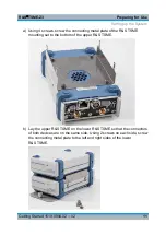
Page 27: ...late of the R S TSME mounting set to the bottom of the upper R S TSME b Lay the upper R S TSME on the lower R S TSME so that the connectors of both devices are on the same side Using 2 screws on each...

Page 28: ...ng the front of the R S TSME 3 Insert the base metal plate with the attached R S TSME s in the mounting rail of the system unit so that the connectors of the R S TSME s are on the same side as the cor...

Page 29: ...onnect each R S TSME to the system unit using a LAN cable and a power supply cable which is provided with the mounting set Fig 3 1 R S TSME Z3 cable connections 7 Connect the control PC for the R S TS...

Page 30: ...de panel of the R S TSME using two screws Fasten one screw in the fourth hole from the left and the other screw in the fourth hole from the right on the R S TSME To fasten the GPS antenna A velcro str...

Page 31: ...igure 3 2 2 Fasten the other side of the velcro strip to the bottom of the GPS antenna 3 Attach the GPS antenna to the velcro strip on the base unit Make sure the antenna cable for the GPS module face...

Page 32: ...ipment to complete the measurement setup for scanning or testing mobile devices To complete the measurement system 1 For scanning a Using a LAN cable connect the control PC for the R S TSME s to the H...

Page 33: ...l DC power supply Connect the DC power supply cable to the DC IN connector on the system unit and the cigarette lighter plug to the external DC power supply To provide power from rechargeable batterie...

Page 34: ...r a low battery charge are indicated by LED signals an acoustic signal or both The fol lowing sections provide information on the possible causes for these warnings and some recommendations how to sol...

Page 35: ...ff No power supplied to the sys tem Connect external power supply or battery and switch on system unit see To switch the system unit on on page 17 Green Unit is supplied with power Yellow Standby due...

Page 36: ...unobstructed Check the connectors of the built in cooling fans to the system unit and make sure they are work ing Open the backpack and let the system cool off 4 2 Acoustic Signals The system unit pro...

Reviews: