System Description
R&S
®
TSME-Z3
6
Getting Started 1519.0994.02 ─ 02
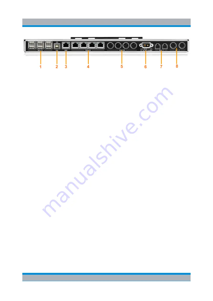
Fig. 2-3: System unit rear panel
1 = USB (type A) connectors for up to 3 mobile devices
2 = CPU: USB (type B) connector for control PC for mobile devices
3 = Host: LAN connector for remote control PC for R&S
TSMEs
4 = LAN connectors for up to 4 R&S
TSMEs
5 = Power supply connectors for up to 4 R&S
TSMEs
6 = DC input connector for external power supply
7 = Fan 1/2: connectors for built-in backpack fans
8 = Bat 1/2: connectors for recharcheable battery adapters 1/2
2.3
Power Supply
The R&S
TSME-Z3 backpack supports two methods of power supply:
●
Portable scanner installation with an external DC source
In this scenario the backpack is used to carry the R&S
TSME and mobile devi-
ces, but is powered from an external DC power source (typically a car bat-
tery). No batteries are required inside the backpack. A DC power supply cable
with a cigarette-lighter plug is provided with the R&S
TSME-Z3.
The external DC power supply connector is protected by a fuse. When power
is supplied to the system unit via the external DC power supply, the PWR LED
lights green.
●
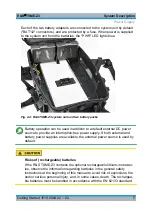
Battery-powered operation
The R&S
TSME-Z3 backpack can be equipped with up to two 91
Wh batteries
(accessory item TSME-Z3B1). The batteries can be hot-swapped, i.e. the
measurement can continue while one empty battery is exchanged by a
charged one. A low battery charge is indicated by an acoustic sound before
the power fails, so the user has enough time to exchange the battery. Further-
more, the battery charge condition is indicated visually on each battery.
The batteries can be charged with a separate AC charger (accessory item
TSME-Z3BC2) that can charge two batteries in parallel (outside the back-
pack).
Power Supply


