background image

Page 

8

 of 16 

Level: 10 / 2020

Enjoy 

your results

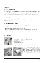
5.8. Mounting the controller on the wall 

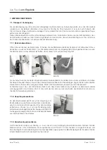
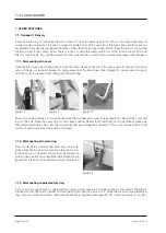
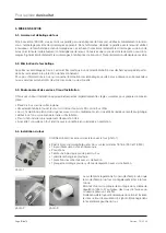
Mounting the controller TC 304 

Choose a safe and easily accessible place on a wall next to the kiln� First screw the two knurled screws into the 
holes indicated on the back of the control unit� They will be used later to fasten the controller in the fixing device� 

Mount the holding bar of the control unit TC 304 using the 3 dowels and 3 screws, so that one fixing hole points 
upwards and the other two point downwards� Make sure that the transparent protective foil is correctly aligned!
 
Now the control unit can be plugged into the fixing device from above� You might have to loosen the knurled screws 
on the controller�

Mounting other TC controllers 

Choose a safe and easily accessible place on a wall next to the kiln� Detach the wall fixing device from the TC control 
unit� Mount the fixing device on to the wall using 2 and 2 screws� Now the control unit can be plugged into the fixing 
device from above� 

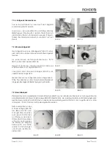
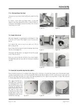
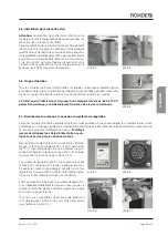
5.9. Kiln and furniture initial firing 

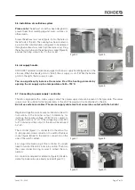
CAUTION: First remove the protective foil from the entire kiln (floor rings and cover)!!! 

Before starting to use the kiln in every day firing, you must carry out a dry firing� For this purpose make sure the ex-
haust air opening on the side of the kiln is open� The "burning-in" by means of a dry firing is important, in order to 
remove residual moisture from the kiln walls� It also generates a protective oxide layer on the heating elements which 
will considerably improve the service life of these components� 

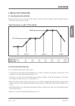
Settings for initial firing:

• heat up at 100° C/ h 
• end temperature 1050°C 
• holding time 1 h 30 min� 

Please note that the service life of the heating elements can be significantly increased by opening the air supply up 
to a temperature of 600-700°C� During the initial firing you can also "burn-in" the hollow stilts and additional furniture 
plates (optional accessories)� For further information please see section 7�3� 
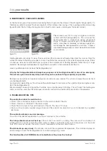
After the first firing, the belts around the cover and the main ring must be retightened� For further information please 
see section 8�0� 

5.10. Instructions power connection / Residual current protective device (RCD) 

If you intend to operate the kiln in workshops or laboratories, a separate power supply with fuse protection must be 
installed by a qualified electrician�

Residual current protective devices (RCD) carrying a tripping current of 0�03 A (such as that used in damp rooms in 
flats) tend to trip early due to the high humidity of the rooms or fired goods� 
A larger sized RCD can be selected (we suggest 0�3 A) provided that the respective circuit is used only for the kiln� 
If this cannot be guaranteed, a fixed power connection must be provided� 

Summary of Contents for Ecotop 20

Page 1: ...C Instruction Manual Electric Toploaders for Ceramics up to 1320 C Mode d emploi Fours électriques verticaux pour la céramique jusqu à 1320 C Istruzioni per l uso Forni elettrici a pozzetto per ceramica fino a 1320 C Manual de instrucciones Horno eléctrico de carga superior para cerámica hasta 1320 C ...

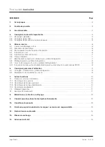
Page 2: ... anschließen 7 5 8 Wandmontage der Regelanlage 8 5 9 Ofen einbrennen Besatz einbrennen 8 5 10 Hinweise Stromanschluss RCD Schutzschalter 8 6 Allgemeine Bedienungshinweise 9 6 1 Bedienungshinweise Regelanlage 9 6 2 Richtiger Umgang beim Brand 9 7 Weitere Funktionen 10 7 1 Transport Verbringung 10 7 1 1 Deckel abmontieren 10 7 1 2 Hauptring demontieren 10 7 1 3 Zwischenring demontieren 10 7 1 4 Fußg...

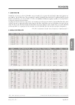
Page 3: ...EE 16 A ø 350 60 Modell Tmax Innenmaß mm Außenmaß mm Leistung Strom Anschluss Besatzplatten Gewicht Volumen C b t h B T H kW A Stecker b x t mm kg TE 75 MCC 1320 ø 470 460 760 730 780 6 0 13 CEE 16 A ø 410 82 ZWR 75 MCC ø 470 230 760 730 230 3 0 23 TE 110 MCC 1320 ø 470 680 760 810 1010 9 0 13 CEE 16 A ø 410 105 TE 100 MCC 1320 ø 520 460 800 800 780 7 0 15 CEE 16 A ø 470 89 ZWR 100 MCC ø 520 230 8...

Page 4: ...Studio Toplader Serie TE MCC Wandaufbau Profi Toplader Serie TE S Wandaufbau Ecotop Toplader Deckelverschluss justier und abschließbar Halbleiterrelais serienmäßig in allen TE S und Ecotop Personenschutzschalter Abluftstutzen Metall Transportgriffe Heizspiralen passgenau fixiert Thermoelement geschützt eingebaut Steinkanten sauber bearbeitet Deckel weit und leicht zu öffnen stabile Aufstellung sta...

Page 5: ... heißem Zustand öffnen Achtung Vor Öffnen des Elektro kastens Netzstecker ziehen Achtung Warnung vor gefährlicher elektrischer Spannung Das CE Zeichen bestätigt dass das Konformitätsbewertungs Verfahren nach EG Richtlinien durch geführt wurde Richtlinie 2004 108 EG Richtlinie 93 68 EWG CE Kenn zeichnung 4 3 Sicherheitshinweise für den Einsatz Nur unter Einhaltung der folgenden Sicherheitshinweise ...

Page 6: ...Sie den Auf stellort entsprechend vor Stellen Sie den Brennofen auf eine ebene Fläche Der Abstand zu Wänden sollte an allen Seiten mindestens 25 cm betragen Der Boden Deckenisolierung Wände Trennwände Verkleidungen etc müssen aus schwer entflammbarem Material sein Achten Sie darauf dass der Aufstellort gut belüftbar ist Andernfalls muss eine Abluftanlage installiert werden Fragen Sie hierzu in jed...

Page 7: ...chlusskabel für Netzanschluss ausgestattet Die entsprechenden Daten können dem Typen schild entnommen werden Die Stromzuführung muss dem Brennofen entsprechend ausgelegt und in unmittel barer Nähe des Brennofens sein Verwenden Sie keinesfalls ein Verlängerungskabel Das Zuleitungskabel darf den heißen Ofen nicht berühren Spannungsschwankungen sind örtlich möglich In Deutschland kann die Nennspannun...

Page 8: ...uluft nicht verschließen Das Einbrennen ist zum einen nötig um Restfeuchtigkeit aus der Ofenwand zu ent fernen zum anderen wird durch dieses Einbrennen eine schützende Oxydschicht auf den Heiz wendeln erzeugt welche die Lebensdauer der Heizwendel entscheidend verlängert Leistungseinstellung für das Einbrennen Aufheizen mit 100 C h Endtemperatur 1050 C Haltezeit 1 Std 30 Min Beachten Sie bitte dass...

Page 9: ...r Umgebungstemperatur von 40 C betrieben werden Der Brennofen muss frei stehen Die Wärmeabstrahlung darf nicht behindert werden Legen Sie keine Gegenstände auf oder am Ofen ab Öffnen Sie keinesfalls den Brennofen solange er noch in Betrieb oder nicht vollständig abgekühlt ist Hohe aus tretende Temperaturen führen zu Brand und Verletzungsgefahr und führen zu vorzeitigem Verschleiß am Ofen Der Herst...

Page 10: ...en Bild 13 mit einem Inbusschlüssel Größe 8 und ziehen Sie beide Schrauben heraus Nun können Sie den Deckel anheben und beiseitelegen Legen Sie den abmontierten Deckel flach auf eine ebene und glatte Fläche Stellen Sie ihn keinesfalls senkrecht auf den Deckelrand Achten Sie darauf dass der Sicherheitsschalter nach dem Zusammenbau des Topladers im Brennraum wieder ordnungsgemäß in das Rundloch fäll...

Page 11: ...enden Sie nun das Fußgestell auf die richtige Arbeits höhe Tauschen Sie nun die entsprechenden Bauteile auf die gegenüberliegenden Befestigungsmöglichkeiten 7 3 Besatzbeispiel Platzieren Sie die 3 mitgelieferten Cordierit Klötzchen Bild 21 auf den Boden des Brennofens dann legen Sie eine erste Besatzplatte optionales Zubehör darauf Bild 22 Beachten Sie dass alle Besatzplatten und Stützen ein gebra...

Page 12: ...b mittels Besen und Staubsauger So verlängern Sie auch die Lebensdauer Ihrer Heizwendel Vermeiden Sie nach Möglichkeit reduzierende Glasurbrände da diese zum Abbau der Oxydationsschicht führen und somit die Lebensdauer der Heizwendel erheblich verkürzen Es ist ratsam ca alle 20 Brände einen Leerbrand ohne Besatz durchzuführen Dabei werden die Heizwendel gesäubert gleichzeitig kann sich die Oxydsch...

Page 13: ...achten Sie bitte Ohne die eingesandte Garantie karte ist eine kostenlose und schnelle Bearbeitung im Schadensfall nicht möglich Achtung Die Feuerleichtsteine der Ausmauerung sind starken Temperaturschwankungen ausgesetzt Dadurch können Haarrisse in der Steinausmauerung entstehen Dieser Vorgang ist normal und beeinträchtigt nicht die Funktion des Ofens Sie sind daher auch kein Anlass für eine Rekla...

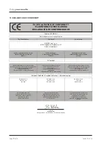
Page 14: ...ing to CE marking Verträglichkeit Directiva 93 68 CEE Denominación CE Richtlinie 93 68 EWG CE Kennzeichnung European Standard Europäische Normen Normas europeas EN 60204 1 ed 2 EN 60439 1 ed 2 EN 61000 6 4 ed 2 EN 55011 ed 2 EN ISO 13732 1 ISO 11684 ISO 7000 EN 60519 1 ed 2 EN 60519 2 ed 2 Documentation evidencing Die oben genannte Firma hält La empresa mencionada anteriormente conformity with the...

Page 15: ...aten welche für eine rasche und genaue Ersatzteilbestellung erforderlich sind 14 SERVICE ADRESSEN Bei Fragen zu Ihrem Brennofen Ersatzteilen oder weiterem Zubehör wenden Sie sich bitte an Ihren Fachhändler Wir wünschen Ihnen viel Erfolg und immer gute Brennergebnisse Ihr ROHDE Team Helmut Rohde GmbH Ried 9 D 83134 Prutting info rohde online net www rohde online net ...

Page 16: ...Seite 16 von 16 Stand 10 2020 Aus Freude am Ergebnis ...

Page 17: ...english Instruction Manual Electric Toploaders for Ceramics up to 1320 C ...

Page 18: ... controller on the wall 24 5 9 Kiln and furniture initial firing 24 5 10 Instructions power connection Residual current protective device RCD 24 6 General operating instructions 25 6 1 Operating instructions Controller 25 6 2 Correct operation during firing 25 7 Other features 26 7 1 Transport Delivery 26 7 1 1 Dismounting kiln cover 26 7 1 2 Dismounting kiln main ring 26 7 1 3 Dismounting supplem...

Page 19: ... 25 TE 190 MCC 1320 ø 590 680 860 940 1010 11 0 16 CEE 16 A 540 125 TE 200 MCC 1320 ø 740 460 1020 1010 780 9 2 20 CEE 32 A Cut to size 130 ZWR 200 MCC ø 740 230 1020 1010 230 4 6 32 TE 300 MCC 1320 ø 740 680 1030 1030 1010 13 8 20 CEE 32 A Cut to size 70 Model Tmax Int dimensions mm Ext dimensions mm Output Supply Connector Furniture batts Weight Volume C w d h W D H kW A Plug w x d mm kg Ecotop ...

Page 20: ...ucture Toploader studio series TE MCC Wall structure Toploader professional series TE S 3 layer wall structure Ecotop Adjustable and lockable cover sealing Solid State Relays standard for all TE S and Ecotop models Safety switch Exhaust air socket Metal handles for transport Heating elements fixed in exact position Thermocouple installed in a safe position Tidy brick edges Cover can be opened easi...

Page 21: ...ty instructions are carefully followed When operated industrially the kiln and controller must undergo a safety check to ensure correct functionality This should be carried out by a qualified electrician before the initial operation and then at 4 year intervals in accordance with DGUV Regulation 3 Deutsche Gesetzliche Unfallversicherung German Social Accident Assurance Maintenance and repair of el...

Page 22: ...iln please note the following guidelines and prepare the kiln environment accordingly Place the kiln on an even surface The distance to the walls should be at least 25 cm on each side The floor ceiling insulation walls dividing walls panelling etc must be made of flame resistant material Make sure that the kiln environment can be properly ventilated Otherwise a ventilation system must be installed...

Page 23: ... kiln is equipped with a mains supply cable The power supply data can be seen on the type plate The power supply must be suitable for the requirements of the kiln The plug must be located next to the kiln Do not use extension cables The mains supply cable must not come into contact with the hot kiln Regional voltage fluctuations are possible and will lead to fluctuations in the nominal output In G...

Page 24: ...ir opening on the side of the kiln is open The burning in by means of a dry firing is important in order to remove residual moisture from the kiln walls It also generates a protective oxide layer on the heating elements which will considerably improve the service life of these components Settings for initial firing heat up at 100 C h end temperature 1050 C holding time 1 h 30 min Please note that ...

Page 25: ...ure of 40 C The kiln must be placed in a free standing position in the room Make sure that the heat release is not blocked Do not place any objects on top of or around the kiln Never open the kiln during operation or before it has cooled down completely High temperatures are released and might cause physical injury and material damage The manufacturer of the kiln does not assume any liability in s...

Page 26: ...it from falling onto the main ring Now use a size 8 Allen key to loosen and remove the two hexagon socket screws figure 13 Now lift the cover and lay it to the side Place the cover on a smooth even surface Never stand it vertically on its side Please make sure that safety switch drops back into the round hole after assembling the Toploader If this is not checked the kiln will switch off and an err...

Page 27: ...d into the correct height Change the respective components to the opposing fixing devices 7 3 Example for positioning furniture plates Place the enclosed 3 small cordierite blocks figure 21 on the floor of the kiln then place one of the furniture plates optional equipment accessory on top figure 22 Please note that all plates and stilts must be burnt in see section 5 9 Do not place the plates too ...

Page 28: ...d allow you to continue firing as quickly as possible Remove clay and stone dust regularly using a broom and a vacuum cleaner This will also increase the service life of your heating elements Avoid reduction glaze firing as this will cause the oxidation layer to decompose thus significantly reducing the service life of the heating elements We recommend an empty firing without furniture or goods af...

Page 29: ...e note If you do not send back the Guarantee Card we will not be able provide quick free support in an event of damage PLease note The firebricks of the kiln lining are exposed to significant temperature fluctuations This may cause hairline cracks in the firebrick lining This process is common and does not affect the functionality of the kiln It cannot therefore be accepted as a reason for complai...

Page 30: ...irective 93 68 ECC relating to CE marking Verträglichkeit Directiva 93 68 CEE Denominación CE Richtlinie 93 68 EWG CE Kennzeichnung European Standard Europäische Normen Normas europeas EN 60204 1 ed 2 EN 60439 1 ed 2 EN 61000 6 4 ed 2 EN 55011 ed 2 EN ISO 13732 1 ISO 11684 ISO 7000 EN 60519 1 ed 2 EN 60519 2 ed 2 Documentation evidencing Die oben genannte Firma hält La empresa mencionada anteriorm...

Page 31: ...a which will allow you to quickly order any spare parts 14 CONTACTS ASSISTANCE If you have any questions regarding your kiln spare parts and additional equipment please contact your local dealer Enjoy working with your new kiln We wish you excellent firing results Your ROHDE team Helmut Rohde GmbH Ried 9 D 83134 Prutting info rohde online net www rohde online net ...

Page 32: ...Page 16 of 16 Level 10 2020 Enjoy your results ...

Page 33: ...français Mode d emploi Fours électriques verticaux pour la céramique jusqu à 1320 C ...

Page 34: ... de rodage du four et du matériel d enfournement 8 5 10 Indications relatives au branchement électrique et au disjoncteur à courant résiduel RCD 8 6 Consignes générales d utilisation 9 6 1 Consignes d utilisation du système de régulation 9 6 2 Maniement correct pendant la cuisson 9 7 Autres fonctions 10 7 1 Transport sur le lieu d installation 10 7 1 1 Démontage du couvercle 10 7 1 2 Démontage de ...

Page 35: ...20 ø 590 460 860 880 780 7 3 16 32 CEE 16 A 540 106 ZWR 130 MCC ø 590 230 860 880 230 3 7 25 TE 190 MCC 1320 ø 590 680 860 940 1010 11 0 16 48 CEE 16 A 540 125 TE 200 MCC 1320 ø 740 460 1020 1010 780 9 2 20 40 CEE 32 A Spécial 130 ZWR 200 MCC ø 740 230 1020 1010 230 4 6 32 TE 300 MCC 1320 ø 740 680 1030 1030 1010 13 8 20 60 CEE 32 A Spécial 170 Modèle Tmax Dimensions int mm Dimensions ext mm Puiss...

Page 36: ... la série verticale artisanale TE MCC Structure des parois de la série verticale professionnelle TE S Structure des parois de la série verticale Ecotop Fermeture du couvercle réglable et verrouillable Relais à semi conducteurs SSR de série sur tous les modèles TE S et Ecotop Disjoncteur de protection à courant de défaut Manchon de sortie d air Poignées de transport métalliques Fixation précise des...

Page 37: ...tier électrique Attention mise en garde contre une tension électrique dangereuse Le marquage CE confirme que la procédure d évaluation de la confor mité a été appliquée suivant les directives européennes suivantes Directive 2004 108 CE Directive 93 68 CEE marquage CE 4 3 Consignes de sécurité pour la mise en œuvre Le four ROHDE ne peut être utilisé sans danger que si les consignes de sécurité suiv...

Page 38: ...oprié et respectez impérativement les règles suivantes pour préparer la mise en place Placez le four sur une surface plane L écartement entre le four et les murs doit être d au moins 25 cm de tous côtés Le sol l isolation du plafond ainsi que les murs cloisons revêtements etc doivent être réalisés en matériau ignifuge Veillez à ce l on puisse bien aérer le lieu d installation Il faut sinon install...

Page 39: ...connexion du système de régulation Le four est équipé d un câble permettant de le raccorder au réseau Vous pouvez relever les caractéristiques corres pondantes sur la plaque signalétique L alimentation électrique doit être dimensionnée en adéquation avec le four et se trouver à proximité immédiate de celui ci N utilisez jamais de rallonges Le câble d alimentation ne do it pas toucher les parois ch...

Page 40: ... rodage est d une part né cessaire pour éliminer l humidité résiduelle des parois du four et elle crée d autre part une couche d oxyde protec trice sur les résistances contribuant à prolonger leur durée de vie de manière décisive Réglage de la puissance pour la cuisson de rodage Chauffer à 100 C h Température finale 1050 C Temps de maintien 1 h 30 min Nota en laissant le trou d évacuation d air ou...

Page 41: ...érature ambiante de 40 C L emplacement choisi pour la mise en place du four doit être bien dégagé Le rayonnement thermique ne doit pas être entravé Ne déposez aucun objet sur le four ni à côté N ouvrez jamais le four tant qu il est encore en service ou qu il n est pas encore complètement refroidi En effet les températures élevées produites par le four peuvent être source d incendie et de blessures...

Page 42: ...format 8 puis retirez ces deux vis Vous pouvez maintenant soulever le couvercle et le déposer sur le côté Le couvercle déposé doit être posé à plat sur une surface plane et lisse Ne le posez jamais sur chant à la verticale Après avoir remonté le four vertical veillez à ce que l interrupteur de sécurité vienne à nouveau se positionner cor rectement dans le trou rond dans la chambre de cuisson À déf...

Page 43: ...té opposé au niveau des points de fixation correspondants les composants que vous venez de démonter 7 3 Exemple d enfournement Placez les 3 petits blocs de cordiérite fournis avec l équipement photo 21 sur la sole du four puis posez une pre mière plaque d enfournement accessoire en option dessus photo 22 Notez que toutes les plaques d enfournement et tous les supports doivent avoir subi une cuisso...

Page 44: ...n aspirateur pour éliminer la poussière d argile et de pierre Ainsi vous prolongez également la durée de vie de vos résistances Évitez dans la mesure du possible les cuissons réductrices car celles ci entraînent une diminution de la couche d oxyde réduisant ainsi considérablement la durée de vie des résistances Il est conseillé de procéder à une cuisson à vide sans matériel d enfournement toutes l...

Page 45: ... pas assurer un traitement rapide et gratuit du dommage signalé Attention les briques réfractaires légères du revêtement intérieur sont soumises à de fortes variations de température Ceci peut provoquer des microfissures dans le revêtement intérieur en brique Ce phénomène est normal et n est aucunement préjudiciable au bon fonctionnement du four Par conséquent ces microfissures ne peuvent donner l...

Page 46: ...ing to CE marking Verträglichkeit Directive 93 68 CEE Marquage CE Richtlinie 93 68 EWG CE Kennzeichnung European Standard Europäische Normen Normes européennes EN 60204 1 ed 2 EN 60439 1 ed 2 EN 61000 6 4 ed 2 EN 55011 ed 2 EN ISO 13732 1 ISO 11684 ISO 7000 EN 60519 1 ed 2 EN 60519 2 ed 2 Documentation evidencing Die oben genannte Firma hält La société susmentionnée tient à disposition conformity ...

Page 47: ...ur nécessaires pour une commande rapide et précise des pièces de rechange 14 ADRESSES DU S A V Pour toute question relative à votre four aux pièces de rechange ou à d autres accessoires veuillez vous adresser à votre revendeur spécialisé Nous vous souhaitons beaucoup de succès et d excellents résultats de cuisson Votre équipe ROHDE Helmut Rohde GmbH Ried 9 D 83134 Prutting info rohde online net ww...

Page 48: ...Page 16 de 16 Version 10 2020 Pour le plaisir du résultat ...

Page 49: ...italiano italiano Istruzioni per l uso Forni elettrici a pozzetto per ceramica fino a 1320 C ...

Page 50: ...ione a parete del regolatore 8 5 9 Cottura iniziale del forno e della carica del forno 8 5 10 Avvertenze per l alimentazione elettrica RCD Interruttore di sicurezza 8 6 Istruzioni d uso generali 9 6 1 Funzionamento del regolatore 9 6 2 Utilizzo corretto durante la cottura 9 7 Funzioni ulteriori 10 7 1 Trasporto al ambiente per l installazione 10 7 1 1 Rimuovere il coperchio 10 7 1 2 Rimuovere l an...

Page 51: ... 760 760 800 800 800 860 860 860 1020 1020 1030 730 730 810 800 800 870 880 880 940 1010 1010 1030 780 230 1010 780 230 1000 780 230 1010 780 230 1010 6 0 3 0 9 0 7 0 3 5 10 5 7 3 3 7 11 0 9 2 4 6 13 8 CEE 16 CEE 16 CEE 16 CEE 16 CEE 16 CEE 16 CEE 32 CEE 32 Ø 410 Ø 410 Ø 470 Ø 470 Ø 540 Ø 540 speciale speciale 82 23 105 89 20 109 106 25 125 130 32 170 13 13 15 15 16 16 20 20 Modello Tmax Dim inter...

Page 52: ...tta la serie a pozzetto Struttura delle pareti della serie TE MCC Struttura delle pareti dei forni professionali serie TE S Struttura delle pareti della serie Ecotop La serratura del coperchio può essere chiusa a lucchetto Relé allo stato solido SSR di serie su tutti i modelli TE S e Ecotop Interruttore salvavita Raccordo per aria esausta Maniglie in metallo per il trasporto Elementi riscaldanti p...

Page 53: ...ne staccare la spina prima di aprire la scatola degli interruttori Attenzione pericolo di tensione elet trica Il simbolo CE conferma che le procedure di valutazione sono state eseguite in conformità alle direttive dell Unione europea Direttiva 2004 1008 CE Direttiva 93 68 CEE marchio CE 4 3 Istruzioni di sicurezza per l uso Il forno a pozzetto ROHDE può essere utilizzato senza pericoli solo se le ...

Page 54: ...riato attenetevi alle istruzioni seguenti e preparate la zona di installazione adeguatamente Posizionare il forno a pozzetto su una superficie piana La distanza dalle pareti deve essere di almeno 25 cm Il pavimento l isolamento del soffitto le pareti divisorie i rivestimenti ecc devono essere di materiale difficilmente infiammabile Nota il luogo per l installazione deve essere ben ventilato In cas...

Page 55: ...nstallazione del regolatore Il forno dispone di un cavo elettrico I dati corrispondenti per l alimentazione elettrica si trovano sulla targhetta L alimentazione elettrica deve essere corrispondente a quella del forno e essere situata nelle immediate vicinanze Non usate mai una prolunga Il cavo di alimentazione non deve toccare il forno bollente Fluttuazioni di tensione sono possibili a livello loc...

Page 56: ...i non chiudere il foro di scarico laterale e la presa d aria La prima cottura è da una parte necessario per rimuovere l umidità residua dalla parete del forno e dall altra per produrre uno strato di ossido protettivo sugli elementi riscaldanti pro lungandone in modo decisivo la durata Impostazioni per la prima cottura Scaldare a 100 C h Portare a una temperatura finale di 1050 C Durata di mantenim...

Page 57: ...Il forno deve essere collocato in una posizione libera dal contatto con altri mobili o oggetti L emisssione termica non deve essere ostacolata Non collocate oggetti sopra al forno Non aprite in nessun caso il forno mentre è ancora in funzione o non è completamente raffreddato La temperatura alta può causare incendi e lesioni corporee o danni prematuri al materiale In tal caso il produttore non si ...

Page 58: ...ra 13 con una chiave a brugola misura 8 e rimuovete en trambi i bulloni Ora è possibile sollevare il coperchio e metterlo da parte Posizionare il coperchio smontato orizzontalmente su una superficie piana e liscia E assolutamente vietato posizionare il coperchio verticalmente sul bordo Dopo l installazione del forno elettrico a pozzetto fate attenzione che l interruttore di sicurezza si reinserisc...

Page 59: ...piedistallo figura 20 Ora girate il piedistallo finché raggiunge l altezza giusta Cambiate ora i rispettivi pezzi sugli strumenti opposti 7 3 Esempio per il caricamento del forno Posizionate i 3 blocchi di cordierite figura 21 sul fondo del forno poi metteteci sopra la prima piastra accessorio opzionale figura 22 Nota tutte le piastre e tutti i supporti devono avere già subito una prima cottura ve...

Page 60: ...ivante dalle argille o dai mattoni usando una scopa e un aspirapolvere In questo modo prolungate anche la durata degli elementi di riscaldamento Evitare se possibile cotture ridotte dello smalto poiché porterebbe a una decomposizione dello strato di ossido e di conseguenza accorcerebbe la durata degli elementi di riscaldamento Si consiglia di effettuare una cottura a vuoto senza carica ogni 20 cot...

Page 61: ...edite la garanzia non ci sarà possibile fornirvi un assistenza veloce e senza costi in caso di danni Attenzione i mattoni del rivestimento refrattario sono esposti a intensi variazioni di temperatura Questo potrebbe causare incrinature al rivestimento refrattario Tale processo è normale e non compromette il funzionamento del forno Essi non rappresentano quindi alcun motivo per un reclamo Cosa fare...

Page 62: ...ica Directive 93 68 ECC relating to CE marking Verträglichkeit Direttiva 93 68 CEE Marchio CE Richtlinie 93 68 EWG CE Kennzeichnung European Standard Europäische Normen Norme europee EN 60204 1 ed 2 EN 60439 1 ed 2 EN 61000 6 4 ed 2 EN 55011 ed 2 EN ISO 13732 1 ISO 11684 ISO 7000 EN 60519 1 ed 2 EN 60519 2 ed 2 Documentation evidencing Die oben genannte Firma hält L impresa nominata qui sopra conf...

Page 63: ...anti che sono necessari per un ordinazione rapida e precisa dei pezzi di ricambio 14 ASSISTENZA In caso di domande riguardo al vostro forno ai pezzi di ricambio o ad accessori vari rivolgersi al proprio rivenditore specializzato Vi auguriamo molto successo e risultati di cottura eccellenti Vostro team ROHDE Helmut Rohde GmbH Ried 9 D 83134 Prutting info rohde online net www rohde online net ...

Page 64: ...Pagina 16 di 16 Versione 10 2020 Godetevi i vostri risultati ...

Page 65: ...Manual de instrucciones Horno eléctrico de carga superior para cerámica hasta 1320 C español ...

Page 66: ...ontaje de pared del controlador 8 5 9 Secado del horno y cocción de la carga 8 5 10 Indicaciones para la conexión de corriente e interruptor diferencial RCD 8 6 Instrucciones generales de manejo 9 6 1 Instrucciones de manejo del controlador 9 6 2 Actuación correcta durante la cocción 9 7 Otras funciones 10 7 1 Transporte y entrega 10 7 1 1 Desmontaje de la tapa 10 7 1 2 Desmontaje del anillo princ...

Page 67: ...60 860 880 780 7 3 16 CEE 16 A ø 540 106 ZWR 130 MCC ø 590 230 860 880 230 3 7 25 TE 190 MCC 1320 ø 590 680 860 940 1010 11 0 16 CEE 16 A ø 540 125 TE 200 MCC 1320 ø 740 460 1020 1010 780 9 2 20 CEE 32 A recorte 130 ZWR 200 MCC ø 740 230 1020 1010 230 4 6 32 TE 300 MCC 1320 ø 740 680 1030 1030 1010 13 8 20 CEE 32 A recorte 70 Modelo Tmáx Medidas interior mm Medidas exterior mm Rendimiento Corrient...

Page 68: ...hornos de carga superior Studio serie TE MCC Estructura de la pared de los hornos de carga superior Profi serie TE S Estructura de la pared del horno de carga superior Ecotop Cierre de la tapa ajustable y cerradero Relés semiconductores SSR de serie en todos los modelos TE S y Ecotop Interruptor de protección para personas Tubo de empalme para el aire de salida Asas metálicas para transporte Resis...

Page 69: ...ón eléctrica peligrosa El certificado CE confirma que el procedimiento evaluador de la conformidad se ha llevado a cabo según las directrices de la Comuni dad Europea Directiva 2004 108 CE Directiva 93 68 CEE certificación CE 4 3 Advertencias de seguridad para su utilización El horno de cocción ROHDE únicamente puede funcionar de forma segura si se respetan las advertencias de seguridad siguientes...

Page 70: ...rmas y preparando el lugar adecuadamente Coloque el horno de cocción sobre una superficie plana La distancia que lo separa de las paredes por todos sus lados debe ser de 25 cm La solera el aislante del techo las paredes las paredes de separación los revestimientos etc deben ser de un material difícilmente inflamable Asegúrese de que el lugar de emplazamiento cuente con suficiente ventilación De lo...

Page 71: ... 5 7 Conexión a la red y conexión del controlador El horno está equipado con un cable de conexión a la red En la placa de características puede consultar los datos pertinentes La acometida de corriente debe ser la adecuada para el horno y estar situada en las inmediaciones de éste Jamás utilice un cable alargador El cable de alimentación no debe tocar el horno caliente Localmente pueden darse osci...

Page 72: ...nar la humedad residual en las paredes del horno y por otra parte este secado genera una capa de óxido protectora en las resistencias que prolongan considerablemente su vida útil Ajuste de la potencia para el secado Calentamiento a 100 C h Temperatura final 1050 C Tiempo de espera 1 h 30 min Recuerde que dejar abierto el orificio de aire de salida hasta aprox los 600 700 C también en las cocciones...

Page 73: ...a 40 C El horno no debe estar apoyado por ninguno de sus lados es decir todo su alrededor debe estar libre La radiación de calor no debe quedar impedida No coloque ningún objeto sobre o dentro del horno No abra bajo ningún concepto el horno mientras esté en servicio o cuando todavía no se ha enfriado por completo Las altas temperaturas que de él emanan pueden causar quemaduras y lesiones y al mism...

Page 74: ...g 13 con una llave Allen de tamaño 8 y extraiga ambos tornillos Entonces puede levantar la tapa y colocarla a un lado Coloque la tapa desmontada plana sobre una superficie llana y lisa Bajo ningún concepto la coloque vertical sobre su borde Una vez haya vuelto a montar la tapa en la cámara de cocción asegúrese de que el interruptor de seguridad vuelve a insertarse en el orificio como corresponde D...

Page 75: ... el bastidor hasta alcanzar la altura de tra bajo adecuada Cambie los componentes correspondientes a los medios de sujeción opuestas 7 3 Ejemplo de carga Deposite los 3 tacos de cordierita suministrados fig 21 sobre la solera del horno y coloque encima una primera placa de carga accesorio opcional fig 22 Tenga en cuenta que todas las placas de carga y soportes deben secarse véase apartado 5 9 Si l...

Page 76: ...de los ladrillos con una escoba o un aspirador De esta forma prolonga la vida útil de las resistencias Evite en la medida de lo posible cocciones reducidas de esmaltes ya que provocan una disminución de la capa de oxidación y por consiguiente acortan considerablemente la vida útil de las resistencias Se aconseja efectuar una cocción en vacío sin carga cada 20 cocciones aprox Este proceso limpia la...

Page 77: ...enta que si no ha enviado la tarjeta de garantía no podrá llevarse a cabo una gestión rápida y gratuita en caso de avería Atención los ladrillos ligeros refractarios del interior del horno están sometidos a fuertes oscilaciones térmicas Por ello pueden producirse grietas muy finas en el interior del horno Este proceso es normal y no repercute en el buen funcionamiento del horno Por consiguiente no...

Page 78: ...93 68 ECC relating to CE marking Verträglichkeit Directiva 93 68 CEE Certificación CE Richtlinie 93 68 EWG CE Kennzeichnung European Standard Europäische Normen Normas europeas EN 60204 1 ed 2 EN 60439 1 ed 2 EN 61000 6 4 ed 2 EN 55011 ed 2 EN ISO 13732 1 ISO 11684 ISO 7000 EN 60519 1 ed 2 EN 60519 2 ed 2 Documentation evidencing Die oben genannte Firma hält La empresa arriba mencionada dispone co...

Page 79: ...ara pedir de forma rápida y exacta piezas de repuesto 14 DIRECCIONES DEL SERVICIO POST VENTA En caso de tener cualquier pregunta acerca de su horno piezas de repuesto u otros accesorios póngase en contacto con su distribuidor Le deseamos mucho éxito y que obtenga siempre los mejores resultados en la cocción Su equipo ROHDE Helmut Rohde GmbH Ried 9 D 83134 Prutting info rohde online net www rohde o...

Page 80: ... 10 2020 broon design ...

Reviews: