background image

Maintenance | 7

KZS-P_KZS-PG

39 / 43

7.3.4

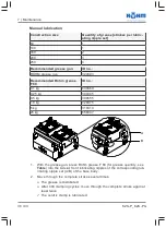
Checking the Clamping Force

Ÿ

Check clamping force with clamping force measurement system.

Recommended clamping force
measurement system

ID no.:

F-Senso Chuck

179800

7.3.5

Complete Cleaning

 CAUTION

Skin irritations due to contact with lubricants.

Lubricants may cause irritations in the event of contact with the skin.

Ø

When handling the 

centric clamp

, wear safety goggles, long

work clothes and gloves.

Ø

Avoid skin contact with lubricants.

For complete cleaning, the centric clamp must be removed from the machine
table, completely dismantled, cleaned and re-assembled.

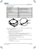
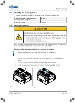
Disassembly and dismantling of the centric clamp

Before dismantling, plan the required time for a leak test.

§

The machine is switched off and protected against being switched on
again.

1.

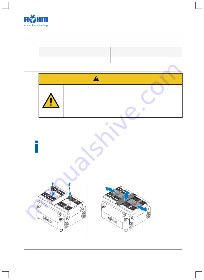
To make all screws accessible, disassemble the top jaws.

2.

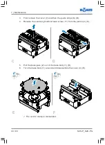
Undo the screws of the cover (7) and of the guide strips (6) (A).

A

B

Summary of Contents for KZS-P

Page 1: ... Straße 50 89567 Sontheim Brenz 49 7325 160 www roehm biz Translation of the Original Operating Manual Power operated Centric Clamp KZS P KZS PG pneumatically operated Version 1 0 26 04 2019 Store for reference ID 1369752 EN ...

Page 2: ......

Page 3: ...2 6 2 Skin Irritation due to Operating Materials 13 2 6 3 Eye Injuries due to Metal Chips 13 2 6 4 Danger of Crushing 14 2 6 5 Procedure in the Event of Danger and Accidents 14 3 Product Description 15 3 1 About this Centric Clamp 15 3 2 Technical Specifications 17 3 2 1 Overview of Construction Sizes 17 3 2 2 Conditions of Use and Environmental Conditions 18 3 2 3 Permissible Operating Materials ...
Page 4: ...p Jaws 32 6 3 Clamping the Workpiece 32 7 Maintenance 34 7 1 Personal Protective Equipment and Personnel Qualification 34 7 2 Maintenance Interval 34 7 3 Maintenance Work 35 7 3 1 Checking the Tightness of Screw Connections 35 7 3 2 Partial Cleaning 36 7 3 3 Lubricating the Centric Clamp 36 7 3 4 Checking the Clamping Force 39 7 3 5 Complete Cleaning 39 8 Storage 42 9 Troubleshooting 42 10 Disposa...

Page 5: ...ite for safe work with the centric clamp In addition to the regulations listed here the local and user related operating instructions and the professional accident prevention regulations are to be observed 1 1 Manufacturer Details RÖHM GmbH Heinrich Röhm Straße 50 D 89567 Sontheim Brenz Germany Tel 49 7325 160 Fax 49 7325 16492 Web www roehm biz E mail info roehm biz 1 2 Copyright This operating m...

Page 6: ... liability for unauthorised replacement and wear parts This applies to both product liability for consequential damage of all types and to liability for damage to property All unauthorised conversions modifications to the centric clamp and or changes in conditions are not permitted for safety reasons and exclude all li ability of RÖHM GmbH for any damage which may result If modifications to the ce...

Page 7: ...g parameters programs etc in particu lar without consulting and obtaining written authorisation from the seller or manufacturer which are due to altered environmental conditions 1 4 Conventions of Presentation 1 4 1 Text Display To improve legibility and comprehension of the text the following conventions were agreed Text type Marking Function Operating instruction 1 2 etc Marks a sequence of acti...

Page 8: ...sonal injury if not avoided Ø List of all measures which must be taken to prevent con sequences WARNING Indicates a possible danger which may lead to permanent personal injury or death if not avoided Ø List of all measures which must be taken to prevent con sequences CAUTION Indicates a possible danger which may lead to minor reversible injuries if not prevented Ø List of all measures which must b...

Page 9: ...orkpieces pendulum jaws inserted horizontally must be used In the case of unmachined parts with a tendency to lift claw jaws must be used The workpieces to be clamped must have a sufficient strength for the clamp ing force and minimum compressibility Other materials may only be used with the agreement of RÖHM GmbH Clamping of imbalanced workpieces is per missible Imbalanced workpieces must always ...

Page 10: ...clamping of other workpieces without the permission of RÖHM GmbH clamping of excessively heavy workpieces for bases of calculation see Röhm norm RN 1391 clamping of excessively long workpieces for bases of calculation see Röhm norm RN 1391 clamping of workpieces with insufficient clamping depth for bases of cal culation see Röhm norm RN 1391 one sided clamping of a workpiece operation without asse...

Page 11: ...el Trained personnel Trained personnel have been instructed in correct handling and possible dangers when using the centric clamp In particular the personnel must have been instructed in the safety equipment Qualified personnel Personnel without experience of handling a centric clamp are exposed to in creased risks of injury in the event of incorrect conduct especially during as sembly and mainten...

Page 12: ...nt posted in the work ing area During rotational operation of the centric clamp KZS P KZS PG no pro tective gloves are to be worn Hand protection is only to be worn during transport assembly and maintenance and as long as the centric clamp KZS P KZS PG is at a standstill Wear protective gloves Wear safety goggles Wear safety shoes Work on and with the centric clamp may only be carried out by quali...

Page 13: ...n effective safety guard 2 6 2 Skin Irritation due to Operating Materials The lubricant consists of substances which may lead to skin irritations in the event of frequent skin contact In order to minimise the risk of skin irritations wear long work clothing and avoid contact with the lubricant Also observe the safety data sheet of the lub ricant and wear safety goggles and protective gloves during...

Page 14: ...ipment with clamping movements where workpiece loading in normal mode is carried out either mechanically or with a ramrod or the object to be clamped is fixed with a permanently or temporarily at tached workpiece holder e g prism before the movement is started or for example in the case of cylinders and comparable moving compon ents the gap is to be covered by a safety guard so as to be inaccessib...

Page 15: ... A Cross section 3 11 22 5 4 17 8 24 1 Basic body 11 Cylinder screw 2 Base jaw 12 Jaw holding screws 3 Piston 14 Countersunk screw 4 Cover 17 Threaded pin 5 Piston disc 22 Rod seal 6 Guide strip 24 Quad ring 7 Cover A Pressure connection close 8 Piston rod not with size 64 B Pressure connection open 10 Cylinder screw ...

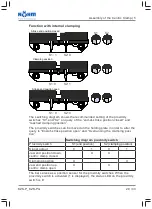
Page 16: ...ys remains central to the middle axis of the centric clamp Various top jaws can be mounted de pending on the workpiece The movement of the centric clamp is controlled via the two pressure connec tions Close and Open with external clamping Pressure connection under pressure Position of the jaws Open Close X Clamping position closed Open Close Sliding freely Open Close X Release position opened Open...

Page 17: ...or in ternal clamping and the clamping position are queried via the proximity switches 44 The proximity switches are equipped with a status LED on the sensor head 3 2 Technical Specifications 3 2 1 Overview of Construction Sizes KZS P standard jaw stroke base jaws with serration 1 5 x 60 and cross tenon ID no 181480 181482 181486 181490 181494 ID no with inductive sensors 181580 181582 181586 1815...

Page 18: ... the following environmental and operating conditions Ambient medium Air and non aggressive gases Place of use Interior Relative humidity at 50 C 100 Use in very humid conditions leads to faster corrosion and may reduce the useful life Potentially explosive environments No Ambient temperature at place of oper ation 10 C to 60 C Ambient temperature for storage 15 C to 60 C For 24 hours also at 70 C...

Page 19: ...Do not remain under suspended loads 4 1 Personal Protective Equipment and Personnel Qualification When working on and with the centric clamp KZS P KZS PG personal pro tective equipment must be worn The owner is responsible for providing per sonal protective equipment Personal protective equipment must be in perfect condition when carrying out work Defective safety equipment is to be replaced immed...

Page 20: ...ist personnel see Qualification of Operating and Special ist Personnel 11 4 2 Tapped Holes for Transport Purposes With a weight of more than 15 kg the centric clamp must be transported with suitable slings KZS P Size 64 100 160 200 250 Weight kg 1 25 3 6 10 3 18 5 30 4 KZS PG Size 100 160 200 250 Weight kg 3 7 10 5 18 9 30 4 ...

Page 21: ...sonal protective equipment 5 1 Personal Protective Equipment and Personnel Qualification When working on and with the centric clamp KZS P KZS PG personal pro tective equipment must be worn The owner is responsible for providing per sonal protective equipment Personal protective equipment must be in perfect condition when carrying out work Defective safety equipment is to be replaced immediately Ob...

Page 22: ...ted directly e g via a pallet direct connection or via pipelines Direct connection In the case of direct connection the centric clamp is supplied with pressure medium via the connections on the underside When using sealing air via a direct connection the connection 5 must be disassembled and the borehole closed with the threaded pin 35 1 2 3 4 1 Pressure connection close 3 Connection for sealing a...

Page 23: ...clamping sleeves There are locating holes on the body for the cylindrical pins and clamping sleeves The machine table must be equipped with coun terparts of the same diameter Positioning with cylindrical pins Positioning with clamping sleeves 5 3 Mounting the Centric Clamp NOTICE Deformation of the cover In the case of excessive actuation pressure the cover of the centric clamp may be deformed Ø F...

Page 24: ...ns on the body see table Remove seals of the connections 3 Place the centric clamp on the assembly surface to test it The body must lie completely and flatly on the surface 4 Depending on the prepared type of positioning use clamping sleeves or cylindrical pins see table Position centric clamp 5 The alignment of the centric clamp can be checked by measuring via the ground flanks on the side of the...

Page 25: ...the centric clamp With clamping sleeves With cylindrical pins a Insert clamping sleeves into the corresponding locating holes on the machine table as far as they will go b Mount in such a way that the pro truding part of the clamping sleeves engages with the locating holes on the body a Insert cylindrical pins into the cor responding locating holes on the machine table as far as they will go b Mou...

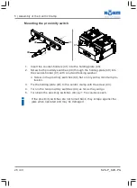
Page 26: ... counter holder 41 with a nut and locking washer Ø Screw in the proximity switches 44 flat or only with a minimum pro trusion 3 Fix the holding plate 40 to the centric clamp with the screw 43 4 Turn in the two proximity switches 44 as far as they will go 5 Turn back the proximity switches 44 by 1 5 revolutions each If the proximity switches are not turned back they scrape against the jaws when ope...

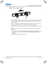
Page 27: ...witching point of the right hand proximity switch S2 so that a switching signal is active in the area of the clamping position 3 Fix the proximity switches with the lock nut Only slightly tighten the lock nut 4 Clamp and open the centric clamp to test the reaction of the proximity switches Ø The status LED on the proximity switch is lit when a signal switching signal 1 is issued see table Switchin...

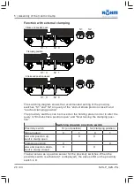
Page 28: ...losed and reached clamping position The proximity switches can be moved on the holding plate in order to alter the query to End of stroke position open and Overrunning the clamping posi tion Switching diagram proximity switch Proximity switch S1 end position S2 clamping position Signal output 0 1 0 1 Jaw end position up centric clamp open X X Clamping position X X Jaw end position down centric cla...

Page 29: ...losed and reached clamping position The proximity switches can be moved on the holding plate in order to alter the query to End of stroke position open and Overrunning the clamping posi tion Switching diagram proximity switch Proximity switch S1 end position S2 clamping position Signal output 0 1 0 1 Jaw end position down centric clamp closed X X Clamping position X X Jaw end position up centric c...

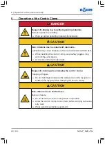
Page 30: ...h the skin Ø When handling the centric clamp wear safety goggles long work clothes and gloves Ø Avoid skin contact with lubricants CAUTION Danger of crushing when clamping the centric clamp Trapping of fingers Ø Do not hold fingers between the workpiece and the top jaws or between the top jaws when clamping the centric clamp CAUTION Risk of Burns due to Hot Surfaces Burns on hands Ø Do not touch t...

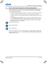
Page 31: ...ipment is to be replaced immediately Observe information on personal protective equipment posted in the work ing area During rotational operation of the centric clamp KZS P KZS PG no pro tective gloves are to be worn Hand protection is only to be worn during transport assembly and maintenance and as long as the centric clamp KZS P KZS PG is at a standstill Wear protective gloves Wear safety goggle...

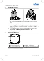
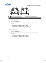
Page 32: ...he jaw fixing screws Observe the labelling of the jaws Top jaw 1 on base jaw 1 top jaw 2 on base jaw 2 2 Tighten the fixing screws with the permissible tightening torque see Checking the Tightness of Screw Connections 35 ü The top jaws are mounted 6 3 Clamping the Workpiece 1 2 3 4 1 Pressure connection close 3 Connection for sealing air 2 Pressure connection open 4 Connections for central lubrica...

Page 33: ...he centric clamp on the pressure connection to open 2 Ø Pressure is built up in the centric clamp Ø The top jaws fix the workpiece from the inside ü The workpiece is clamped Internal clamping 1 Position the workpiece 2 Apply pressure to the centric clamp on the pressure connection to close 1 Ø Pressure is built up in the centric clamp Ø The top jaws fix the workpiece externally ü The workpiece is ...

Page 34: ...to be worn during transport assembly and maintenance and as long as the centric clamp KZS P KZS PG is at a standstill Wear protective gloves Wear safety goggles Wear safety shoes Work on and with the centric clamp may only be carried out by qualified oper ating and specialist personnel see Qualification of Operating and Special ist Personnel 11 7 2 Maintenance Interval The regular maintenance work...

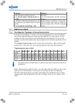
Page 35: ...r of the screw must be used and the tightening torque applied in accordance with the screw quality For cylinder head screws of the conventional sizes M4 M24 and strength classes 8 8 10 9 and 12 9 the following tightening torque table applies Tightening torque in Nm Strength class M4 M5 M6 M8 M10 M12 M14 M16 M18 M20 M22 M24 8 8 3 0 5 9 10 1 24 6 48 84 133 206 295 415 567 714 10 9 4 6 8 6 14 9 36 1 ...

Page 36: ...l cleaning Cleaning with compressed air or a high pressure cleaner is not permitted 1 Remove dirt and swarf towards the drive side with a brush or broom 2 Clean the top jaws with a cloth or brush 3 Thoroughly clean the top jaws with a cloth soaked in petroleum or ben zine 4 Thoroughly clean the centric clamp with a cloth soaked in petroleum or benzine 5 Brush the ground surfaces with acid free oil...

Page 37: ...ral lubrication the threaded pins are removed from the cover the boreholes are sealed with O rings and both supply lines are connected 1 Pour in the oil for oil quantity see Table via both connections of the central lubrication unit 4 on the underside of the base body Ø Each connection supplies a guide of both base jaws for which reason both connections must be connected 2 Move through the complet...

Page 38: ...869 0 25 kg 304345 0 5 kg 308555 1 0 kg 028975 5 kg 318310 25 kg 658047 A B 1 With the grease gun press Röhm grease F 80 for grease quantity see Table into the side or front lubricating nipples of the corresponding lub ricating nipple set A B of the base body 2 Move through the complete stroke several times Ø The grease is distributed Ø After 400 clamping cycles move through the complete stroke ag...

Page 39: ...n Ø When handling the centric clamp wear safety goggles long work clothes and gloves Ø Avoid skin contact with lubricants For complete cleaning the centric clamp must be removed from the machine table completely dismantled cleaned and re assembled Disassembly and dismantling of the centric clamp Before dismantling plan the required time for a leak test The machine is switched off and protected aga...

Page 40: ...over 7 and then the guide strips 6 B 4 Release the central cylindrical head screw 11 from the piston 3 C C D 5 Pull the base jaws 2 out of the base body 1 D 6 Turn the base body 1 around and disassemble the cover 4 E E F ü The centric clamp is dismantled ...

Page 41: ...or benzine and free of grease residue dirt and abrasion ü The centric clamp is cleaned Cleaning with compressed air or a high pressure cleaner is not permitted Lubrication of the centric clamp Brush the individual parts of the dismantled centric clamp with Röhm grease F 80 ü The dismantled centric clamp is lubricated Assembly of the centric clamp The centric clamp is assembled in reverse order Ins...

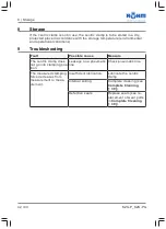
Page 42: ...9 Troubleshooting Fault Possible cause Measure The centric clamp does not go into clamping pos ition Leakage on a pneumatic line Check pneumatic line The measured clamping force decreases from measurement to meas urement Insufficient lubrication Lubricate the centric clamp Internal soiling Complete cleaning see Complete Cleaning 39 Defective seals Replace seals see re placement of wear parts in Co...

Page 43: ...of in an environment ally way in accordance with the valid regulations Metals Metals must be recycled They must be disposed of in accordance with the valid regulations and the applicable local provisions Obtain relevant informa tion from the authorities Plastics They must be disposed of in accordance with the valid regulations and the ap plicable local provisions Obtain relevant information from t...

Reviews: