background image

- iii -

Contents

3.5  Boot ................................................................................................36

3.6  Save & Exit ....................................................................................37

Summary of Contents for QSM-622E

Page 1: ...I QSM 622E User s Manual Version 1 0 2017 05 85 Wide Range Temperature Qseven CPU Module 85 ...

Page 2: ... II This page is intentionally left blank ...

Page 3: ... i Revision History Version Release Time Description 1 0 May 2017 Initial release ...

Page 4: ...ckage 4 1 5 Ordering Information 4 1 6 Optional Accessories 4 1 7 Driver Installation Note 5 Chapter 2 Board Overview 7 2 1 Board Dimensions 8 2 2 Block Diagram 9 2 3 Connector Pin Definition 10 Chapter 3 BIOS 13 3 1 Main 14 3 2 Advanced 16 3 2 1 F81866 Super IO Configuration 17 3 2 2 Hardware Monitor 19 3 2 3 CPU Configuration 20 3 2 4 IDE Configuration 21 3 2 5 LPSS SCC Configuration 22 3 2 6 CS...

Page 5: ... iii Contents 3 5 Boot 36 3 6 Save Exit 37 ...

Page 6: ...CE The CE symbol on your product indicates that it is in compliance with the directives of the Union European EU A Certificate of Compliance is available by contacting Technical Support This product has passed the CE test for environmental specifications when shielded cables are used for external wiring We recommend the use of shielded cables This kind of cable is available from ARBOR Please conta...

Page 7: ...ill be required to correct the interference at his own expense RoHS ARBOR Technology Corp certifies that all components in its products are in compliance and conform to the European Union s Restriction of Use of Haz ardous Substances in Electrical and Electronic Equipment RoHS Directive 2002 95 EC The above mentioned directive was published on 2 13 2003 The main pur pose of the directive is to pro...

Page 8: ... from the power source when you want to work on the inside 2 Hold the board by the edges and try not to touch the IC chips leads or circuitry 3 Use a grounded wrist strap when handling computer components 4 Place components on a grounded antistatic pad or on the bag that comes with the Single Board Computer whenever components are separated from the system Replacing the Lithium Battery Incorrect r...

Page 9: ...omtheuse misuseof orinabilityto usethisproduct Vendorwillnotbeliableforanyclaimmadebyanyotherrelatedparty Vendors disclaim all other warranties either expressed or implied including but not limited to implied warranties of merchantability and fitness for a particular purpose with respect to the hardware the accompanying product s manual s and written materials and any accompanying hardware This li...

Page 10: ... viii This page is intentionally left blank ...

Page 11: ... 1 1 Chapter 1 Introduction Chapter 1 Introduction ...

Page 12: ...g Temp 40 85 C 1 2 About this Manual This manual is intended for experienced users and integrators with hardware knowledge of computers If you are not sure about the description in this manual consult your vendor before further handling We recommend that you keep one copy of this manual for the quick reference for any necessary maintenance in the future Thank you for choosing ARBOR products ...

Page 13: ...C Optional Graphics Interface LCD Dual Channels 24 bit LVDS resolution up to 1920x1200 Analog RGB signals via Qseven GF reserved pin 1 x DDI port Expansion Bus 3 x PCIe x1 lanes I2C Operating Temp 40ºC 85ºC 40ºF 185ºF Humidity 10 95 85ºC non condensing Watchdog Timer 1 255 levels reset Dimension L x W 70 x 70 mm 2 76 x 2 76 Please don t hot plug USB device with USB port0 to avoid that OS can t rec...

Page 14: ... Trail I E3825 Qseven WT CPU module w 2GB memory soldered on module QSM 662E E3845 2G Intel Atom Processor Bay Trail I E3845 Qseven WT CPU mod ule w 2GB memory soldered on module QSM 662E E3845 4G Intel Atom Processor Bay Trail I E3845 Qseven WT CPU mod ule w 4GB memory soldered on module 1 6 Optional Accessories HS 0662 F1 Heat spreader HS 0000 W3 Universal evaluation Heatsink for Qseven CPU modu...

Page 15: ...ind the drivers on CD by the following paths Windows 8 1 Driver Path Audio Audio 32 bit Audio 64 bit Chipset Chipset 32bit Chipset Kit 57833 _32 Chipset 64bit Chipset Kit 57833 _64 Ethernet Ethernet Intel 32bit LAN 18 8 1 _32 Ethernet Intel 64bit LAN 18 8 1 _64 GPIO I2C GPIO I2C windows 8 32_64 Intel_Processor_Win8_IO_Drivers_ Gold_MR1 Graphics Graphic win32_153339 Graphic win64_153339 MBI MBI MBI...

Page 16: ...2 Chipset 64bit Chipset Kit 57833 _64 Ethernet Ethernet Intel 32bit LAN 18 8 1 _32 Ethernet Intel 64bit LAN 18 8 1 _64 Graphics Graphic win32_153339 Graphic win64_153339 GPIO I2C GPIO I2C windows 7 32_64 Intel_Atom_E3800_Processor_Win7_ IO_Drivers_MR1_v4_0 TXE TXE TXE Kit 100885 USB3 0 USB3 0 SetupUSB3 WINUSB USB ...

Page 17: ... 7 2 Chapter 2 Board Overview Chapter 2 Board Overview ...

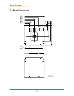
Page 18: ... 8 Board Overview 2 1 Board Dimensions 22 86 36 58 35 94 15 77 39 27 1 20 18 00 52 00 70 00 3 00 67 00 2 50 70 00 56 50 Unit mm ...

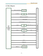
Page 19: ...port USB1 1 2 0 1 x HSIC SMSC USB4604 LPC I F 4 x USB 2 0 host ports Support USB2 0 only HD Audio Link SATA0 SATA1 1 x PCIe x 1 GbE GbE Controller Intel i210IT Analog R G B to Q7 RSV pin DDR3L 1066 1333 MT s Onboard DDR3L 2GB SDRAM 1 x DDI port DDI1 1 x eDP port Intel Atom Processor E3800 family eMMC 4 5 Onboard eMMC up to 16GB ...

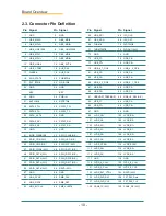
Page 20: ... SDIO_DAT6 N C 56 RSVD N C 57 GND 58 GND 59 HDA_SYNC 60 SMB_CLK 61 HDA_RST 62 SMB_DAT 63 HDA_BITCLK 64 SMB_ALERT Pin Signal Pin Signal 65 HDA_SDI 66 I2C_CLK 67 HDA_SDO 68 I2C_DAT 69 THRM 70 WDTRIG 71 THRMTRIP 72 WDOUT N C 73 GND 74 GND 75 USB_P7 76 USB_P6 77 USB_P7 78 USB_P6 79 USB_6_7_OC 80 USB_4_5_OC 81 USB_P5 82 USB_P4 83 USB_P5 84 USB_P4 85 USB_2_3_OC 86 USB_0_1_OC 87 USB_P3 88 USB_P2 89 USB_P...

Page 21: ...IE2_TX 168 PCIE2_RX 169 PCIE2_TX 170 PCIE2_RX 171 EXCD0_PERST 172 EXCD1_PERST 173 PCIE1_TX 174 PCIE1_RX 175 PCIE1_TX 176 PCIE1_RX 177 EXCD0_CPPE 178 EXCD1_CPPE 179 PCIE0_TX 180 PCIE0_RX 181 PCIE0_TX 182 PCIE0_RX 183 GND 184 GND 185 LPC_AD0 186 LPC_AD1 187 LPC_AD2 188 LPC_AD3 189 LPC_CLK 190 LPC_FRAME 191 SERIRQ 192 LPC_LDRQ N C 193 VCC_RTC 194 SPKR 195 FAN_TACHOIN N C 196 FAN_PWMOUT N C Pin Signal...

Page 22: ... 12 This page is intentionally left blank ...

Page 23: ... 13 Chapter 3 BIOS 3 Chapter 3 BIOS ...

Page 24: ...ion 9 01 Build Date and Time 11 25 2016 19 07 03 CPU Configuration Microcode Patch 907 BayTrail SoC D0 Setpping Memory Information Total Memory 4098 MB DDR3L TXE Information Sec RC Version 00 05 00 00 TXE FW Version 01 00 52 1129 System Language English System Date Fri 01 06 2017 System Time 01 39 30 Set the Date Use Tab to Switch between Date elements Select Screen Select Item Enter Select Change...

Page 25: ...main menu Page Up Increase the numeric value on a selected setup item make change Page Down Decrease the numeric value on a selected setup item make change F1 Activate General Help screen F10 Save the changes that have been made in the setup and exit a message screen will display and ask you to select OK or Cancel for exiting and saving changes Use and to select and press Enter to confirm Key Comm...

Page 26: ...ge Opt F1 General Help F2 Previous Values F9 Optimized Defaults F10 Save and Exit ESC Exit Advanced Chipset Security Save Exit Main Boot Setting Description F81866 Super IO Configuration See section 3 2 1 F81866 Super IO Configuration Hardware Monitor See section 3 2 2 Hardware Monitor CPU Configuration See section 3 2 3 CPU Configuration IDE Configuration See section 3 2 4 IDE Configuration LPSS ...

Page 27: ...revious Values F9 Optimized Defaults F10 Save and Exit ESC Exit Advanced Aptio Setup Utility Copyright C 2016 American Megatrends Inc Version 2 17 1255 Copyright C 2016 American Megatrendes Inc Setting Description Serial Port Enable default or Disable Serial Port COM Select an optimal setting for Super IO device Options for Serial Port 1 COMA Auto default IO 3F8h IRQ 4 IO 3F8h IRQ 3 4 5 6 7 9 10 1...

Page 28: ...3 4 5 6 7 9 10 11 12 Options for Serial Port 5 COME Auto default IO 2E0h IRQ 7 IO 3E8h IRQ 3 4 5 6 7 9 10 11 12 IO 2E8h IRQ 3 4 5 6 7 9 10 11 12 IO 2F0h IRQ 3 4 5 6 7 9 10 11 12 IO 2E0h IRQ 3 4 5 6 7 9 10 11 12 Options for Serial Port 6 COMF Auto default IO 2E0h IRQ 7 IO 3E8h IRQ 3 4 5 6 7 9 10 11 12 IO 2E8h IRQ 3 4 5 6 7 9 10 11 12 IO 2F0h IRQ 3 4 5 6 7 9 10 11 12 IO 2E0h IRQ 3 4 5 6 7 9 10 11 12...

Page 29: ...eed N A 1 5V 1 528 V 5VSB 5 003 V 5V 4 961 V 12V 12 144 V LM90 Thermal Sensor Local temperature 49 C Remote temperature 46 000 C Select Screen Select Item Enter Select Change Opt F1 General Help F2 Previous Values F9 Optimized Defaults F10 Save and Exit ESC Exit Advanced Aptio Setup Utility Copyright C 2016 American Megatrends Inc Version 2 17 1255 Copyright C 2016 American Megatrendes Inc Access ...

Page 30: ...sable Bit Enabled Intel Virtualization Enabled Socket specific CPU Information Setting Description Socket 0 CPU Information Display Socket specific CPU Information CPU Thermal Configuration CPU Thermal Configuration options DTS Enable or Disable default Digital Thermal Sensor Limit CPUID Maximum Enable or Disable default the maximum CPUID value limit Disable this item to prevent the system from re...

Page 31: ... 21 BIOS Intel Virtualization Enable default or Disable the Intel Virtualization Technology When enabled a VMM can utilize the additional hardware capabilities provided by Vandor Pool Technology ...

Page 32: ... F2 Previous Values F9 Optimized Defaults F10 Save and Exit ESC Exit Advanced Enable Disable Serial ATA Aptio Setup Utility Copyright C 2016 American Megatrends Inc Version 2 17 1255 Copyright C 2016 American Megatrendes Inc Setting Description Serial ATA SATA Enable default or disable SATA Device SATA Test Mode Enable or disable default test mode SATA Speed Support Select SATA Speed Support Optio...

Page 33: ...Copyright C 2016 American Megatrends Inc Advanced Aptio Setup Utility Copyright C 2016 American Megatrends Inc Select Screen Select Item Enter Select Change Opt F1 General Help F2 Previous Values F9 Optimized Defaults F10 Save Exit ESC Exit Setting Description OS Selection Select the OS Options Windows 8 X Android Windows 7 default LPSS SCC Devices Mode Set the LPSS SCC Devices Mode Options ACPI m...

Page 34: ...default eMMC 4 5 DDR50 support SCC eMMC 4 5 HS200 Su Only available when SCC eMMC support is set to Enable eMMC 4 5 Support or eMMC Auto Mode Enable or Disable default eMMC 4 5 HS200 support LPSS Configuration LPSS DMA 1 2 Support Enable or Disable default LPSS DMA 1 2 support LPSS I2C 1 Support Enable or Disable default LPSS I2C support ...

Page 35: ...cy default Legacy only UEFI only Network Control the execution of UEFI and Legacy PXE OpROM Options Do not launch UEFI default and Legacy Aptio Setup Utility Copyright C 2016 American Megatrends Inc Version 2 17 1255 Copyright C 2016 American Megatrendes Inc Compatibility Support Module Configuration CSM Support CSM16 Module Version GateA20 Active Option ROM Messages Boot option filter Option ROM ...

Page 36: ...not launch UEFI default and Legacy Video Control the execution of UEFI and Legacy Video OpROM Options Do not launch UEFI and Legacy default Other PCI devices Determines OpROM execution policy for devices other than network storage or video Options Do not launch UEFI default and Legacy ...

Page 37: ...t F1 General Help F2 Previous Values F9 Optimized Defaults F10 Save and Exit ESC Exit Advanced Enabled Enabled Enabled 20 sec 20 sec Auto Aptio Setup Utility Copyright C 2016 American Megatrends Inc Version 2 17 1255 Copyright C 2016 American Megatrendes Inc 3 2 7 USB Configuration Setting Description Legacy USB Support Sets legacy USB support Options Enabled default Disabled and Auto AUTO option ...

Page 38: ...me out Options 10 sec 20 sec default 30 sec 40 sec Device power up delay Use this item to set maximum time the device will take before it properly reports itself to the host controller Options Auto Default Auto uses default value for a root port it is 100 ms for a hub port the delay is taken from hub descriptor Manual Select Manual you can set value for the following sub item Device Power up delay...

Page 39: ...nc Boot Security Save Exit North Bridge Parameters Select Screen Select Item Enter Select Change Opt F1 General Help F2 Previous Values F9 Optimized Defaults F10 Save and Exit ESC Exit North Bridge South Bridge Main Advanced Chipset Setting Description North Bridge See section 3 3 1 North Bridge South Bridge See section 3 3 2 South Bridge ...

Page 40: ...ics Power Management Control Memory Information Total Memory 4096 MB DDR3 Memory Slot0 4096 MB DDR3 Max TOLUD 2GB Chipset Config Intel IGD Settings The featured settings are Setting Submenu Description Intel IGD Configuration See secion 3 3 1 1 Intel IGD Configuration IGD LCD Control See secion 3 3 1 2 LCD Control Graphics Power Management Control RC6 Render Standby Enable default or Disable rende...

Page 41: ...rnal Graphic Device Options 64M is the default DVMT Total Gfx Mem Select the DVMT 5 0 Total Graphic Memory size used by the Internal Graphic Device Options 128MB 256MB default and Max Apeture Size Select the Apeture Size Options 128MB 256MB default and 512MB DOP CG Enable default or Disable DOP Clock Gating GTT Size Select the GTT Size Options 1MB and 2MB default IGD Thermal Enable or Disable defa...

Page 42: ...t LCD panel used by Internal Graphics Device by selecting the appropriate setup item Default is 800 x 480 LVDS LVDS Channel Type Select single or dual channel Options Dual and Single default LVDS Panel Color Format Select LVDS color display mode Options 18 BIT default 24 BIT ...

Page 43: ...te Enabled Azalia HD Audio Options Setting Description Azalia Configuration See section 3 3 2 1 Azalia HD Configuration USB Configuration See section 3 3 2 2 USB Configuration PCI Express Configuration See section 3 3 2 3 PCI Express Configuration High Precision Timer Enable default or Disable the High Precision Event Timer Restore AC Power Loss Select AC power state when power is re applied after...

Page 44: ...will be unconditonally enabled Auto Azalia will be enabled if present disabled otherwise Azalia VCi Enable Enable default or Disable Virtual Channel 1 of Audio Controller Azalia Docking Enable or Disable default Azalia docking support of audio controller Azalia PME Enable Enable default or Disable Power Management capability of Audio Controller Azalia HDMI Codec Enable default or Disable internal ...

Page 45: ...ult in HOST mode It should be OFF in OTG device mode XHCI Mode Set the mode of operatin of xHCI Mode Options Enabled Disabled Auto and Smart Auto default USB2 Link Power Management Enable or Disable default USB2 Link Power Management USB Per Port Control Enable default or Disable USB per port control USB Port 0 1 2 3 Enable default or Disable USB port 0 1 2 3 ...

Page 46: ...ed Extra Bus Reserved for bridges behind this Root Bridge Options 0 3 Default 1 for PCI Express port 0 0 for PCI Express port 1 2 3 Reserved Memory Reserved Memory Range for this Root Bridge Default 10 Reserved Memory Alignment Reserved Memory Alignment 0 31 bits Default 1 Perfetchable Memory Perfetchable Memory Range for this Root Bridge Default 10 Perfetchable Memory Alignment Perfetchable Memor...

Page 47: ...strator rights The password length must be in the following range Minimum length 3 Maximum length 20 Administrator Password User Password Set Administrator Password Chipset Security Save Exit Main Boot The Security menu sets up the administrator password Setting Description Administrator Password To set up an administrator password 1 Select Administrator Password The screen then pops up an Create ...

Page 48: ...Boot Option 1 Select the keyboard NumLock state 1 On Disabled Disabled UEFI Built in EFI Setting Description Setup Prompt Timeout Set the number of seconds to wait for setup activation key 65535 0XFFF means indefinite waiting Default 1 Boot NumLock State Select the keyboard NumLock state Options On default and Off Quiet Boot Enable or Disable default Quiet Boot option Fast Boot Enable or Disable d...

Page 49: ...it system setup after saving the changes Main Boot Security Save Exit Setting Description Save Changes and Exit Exit system setup after saving the changes Enter the item and then a dialog box pops up Save configuration and exit Yes No Discard Changes and Exit Exit system setup without saving the changes Enter the item and then a dialog box pops up Quit without saving Yes No Save Changes and Reset ...

Page 50: ...ops up Save configuration Yes No Restore User Defaults Restore the User Defaults to all the setup op tions Enter the item and then a dialog box pops up Restore User Defaults Yes No UEFI Bulit in EFI Shell Enter the item and then a dialog box pops up Save configuration and reset Yes No Launch EFI Shell from filesystem device Attempts to launch EFI shell application Shell efi from one of the availab...

Reviews: