Installation
- 2.14 -
PCS FS Kit
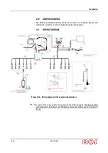
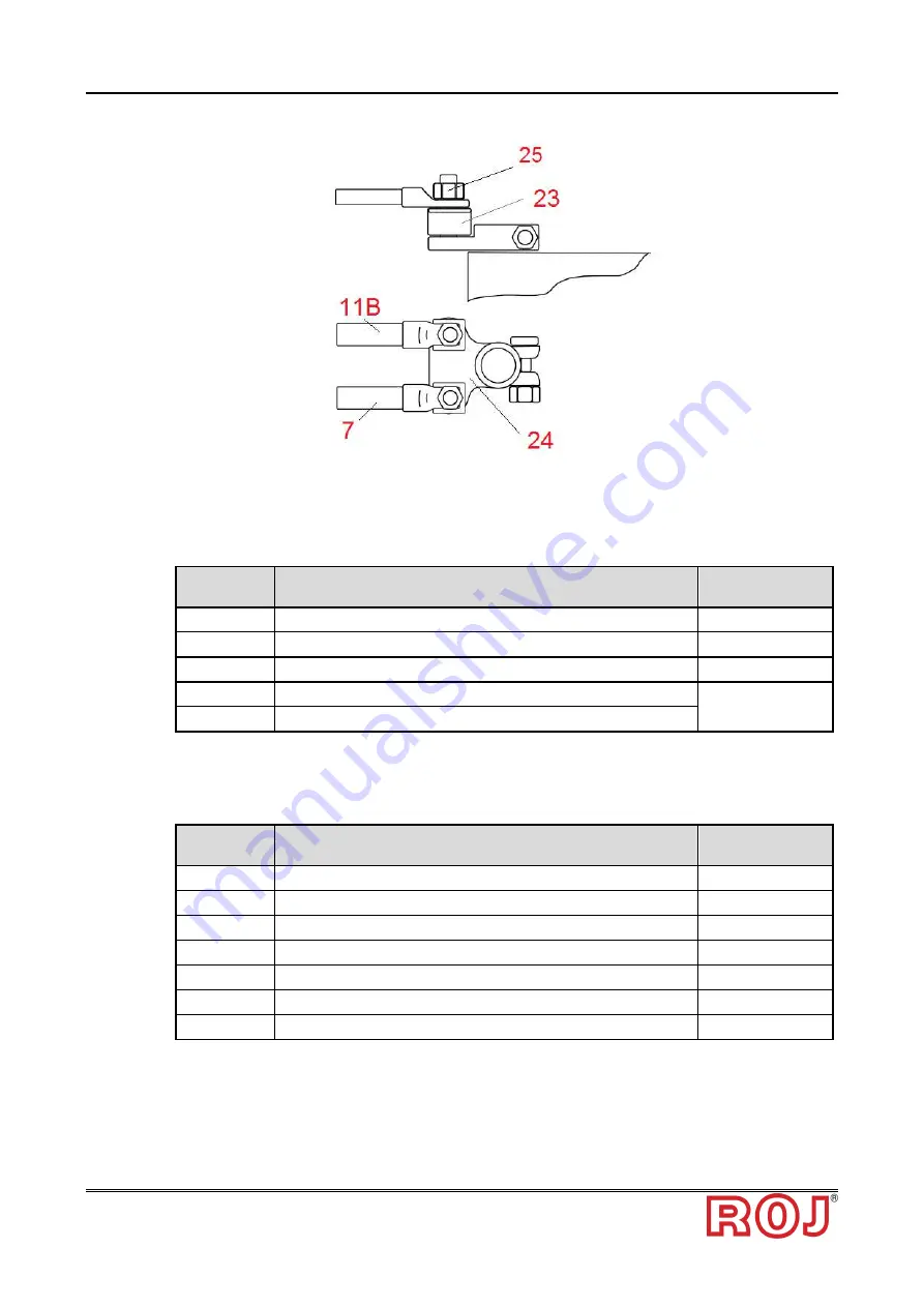
Figure 2-13
–
Battery positive pole connection detail
2.11.1 Main components
Code
Description
Ref. on wiring
diagram
54T01068
DEMETER ECU
1
58G00074
AGRI-MATE GRAPHICAL CONSOLE
2
1406.601
PCS MD-O
3
56C00646
PCS SDB 12+12
4
56C00651
PCS SDB 3 + 3
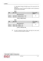
2.11.2 ECU connection
Code
Description
Ref. on wiring
diagram
05R01379
ECU 18P CABLE PCS
12
05R01334
ECU PLUG 30C
20
05R01380
ECU 30P CABLE PCS
21
50A00174
HALL EFFECT SPEED SENSOR GS102301
14
05R01400
GS102301 SPEED SENSOR CABLE L=1500mm
19
05R01422
MECHANICAL SWITCH SENSOR
15
05A00173
PRESSURE SENSOR
22
Summary of Contents for AGRI Mate PCS FS
Page 1: ...PCS FS Installation Operation Maintenance ORIGINAL INSTRUCTIONS ...
Page 7: ......
Page 34: ...Installation PCS FS Kit 2 13 Figure 2 Wiring diagram of the system without alternator ...
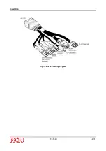
Page 36: ...Installation PCS FS Kit 2 15 Figure 2 14 ECU wiring diagram ...
Page 42: ...Installation PCS FS Kit 2 21 This page is intentionally left blank ...
Page 91: ...User s manual PCS FS Kit 3 49 This page is intentionally left blank ...
Page 94: ...Maintenance and Troubleshooting PCS FS Kit 4 3 4 4 SPARE PARTS ...
Page 99: ...Maintenance and Troubleshooting 4 8 PCS FS Kit This page is intentionally left blank ...


