background image

Installation


PCS FS Kit 

- 2.21 - 

This page is intentionally left blank


Summary of Contents for AGRI Mate PCS FS

Page 1: ...PCS FS Installation Operation Maintenance ORIGINAL INSTRUCTIONS ...

Page 2: ...hange at any time the contents of this manual without notice For any technical or commercial problem please contact your local ROJ dealer or call directly ROJ customer service center We will be glad to meet your needs Thank you for your trust and good job The PCS FS is a patented equipment which employs exclusive and high tech solutions ...

Page 3: ...ALLATION OPERATION AND MAINTENANCE MANUAL Edition January 2019 Revision 1 0 Direction and Plant ROJ Via Vercellone 11 13900 Biella BI Italy Tel 39 015 84 80 111 Fax 39 015 84 80 209 E mail comm roj com www roj it ...

Page 4: ...5 1 4 GENERAL INFORMATION ABOUT SAFETY 1 7 1 4 1 Design criteria 1 7 1 4 2 Safety Devices and Solutions 1 8 1 4 3 Warning about residual risks 1 9 1 4 4 Warnings and Behaviour rules for the Operator 1 9 1 4 5 Noise levels 1 10 1 4 6 Proper and improper use 1 10 1 4 7 Reliability of the safety related control systems 1 10 2 INSTALLATION 2 1 2 1 GEARED MOTOR MD FEATURES 2 1 2 2 MOTORS MD INSTALLATIO...

Page 5: ...3 3 3 4 MOTORS ADDRESSING 3 4 3 4 1 Machine configuration 3 5 3 4 2 Addressing 3 6 3 5 MACHINE CONFIGURATION 3 9 3 6 SEEDING FERTILIZATION SETTINGS 3 14 3 7 HOME 3 21 3 7 1 Group MD exclusion 3 22 3 7 2 Summary information about the seeding fertilization job 3 23 3 7 3 Synoptic Tab 3 24 3 7 4 Seeding fertilization job 3 28 3 8 ALARMS 3 29 3 9 FIRMWARE UPDATE 3 36 3 10 STATISTICS 3 41 3 11 TERMINAL...

Page 6: ...Table of contents PCS FS Kit iii UPDATES INDEX 9 18 2014 1st Edition 3 29 2016 2nd Edition 1 10 2019 3rd Edition Manuals for the different systems 200 FS 150 ...

Page 7: ......

Page 8: ...the Customer 3 ROJ Use and Maintenance manuals contain the information deemed important and necessary by the Manufacturer in order to Correctly understand the functioning principles of the machine Carry out all the handling mounting installation power sources cabling in safe conditions keeping into account the possible dangers related to the above activities and giving directions prescriptions and...

Page 9: ...mits defined by the EN ISO 14982 2009 Harmonized Standard for Industrial Environments The ROJ User and Maintenance Manuals contain the updated list of the harmonized standards applied during the design stage to guarantee the compliance with the Essential Safety Requirement Listed on Annex I of 2006 42 EC Directive while the design and implementation details are described on the Technical File kept...

Page 10: ...O13849 2 2012 EN ISO 4254 1 2015 EN 14018 2010 EN ISO 14982 2009 The equipment complies with the requirements of the 2014 30 EU Directive Note 2 relating to Electromagnetic Compatibility The person authorized to draw up the Technical Documentation is Ing Luca Bagatin luca bagatin roj com ROJ complied with the following EHSRs Essential health and safety requirements Annex 1 of the Machinery Directi...

Page 11: ...FS system components In the event that after an accurate assessment the complaint is deemed admissible ROJ may at its sole discretion replace or repair the defective components Other warranty terms ROJ guarantees the quality and reliability of the equipment that has been designed and manufactured to provide optimal performance The warranty does not cover any damages or indirect costs due to machin...

Page 12: ...nfigure the system and to set up the various operating parameters according to the user s requirements How to carry out the preventive maintenance under safe conditions 1 1 3 How to Use this Manual The manual is divided into four sections Section 1 shows the structure and the components of the system and provides notes and safety warnings in addition to the technical data of the units that are inc...

Page 13: ...European Union and to those countries where a separate collection of waste is in force This symbol on the product or its packaging indicates that the product should not be treated as a normal household waste but must be handed over to an appropriate collection point for the recycling of electrical and electronic equipment By ensuring that this product is properly disposed of you will help prevent ...

Page 14: ...ansfers to MDs both the basic settings and the real time information needed for sowing and fertilizing MD Motor integrated drive used to move the seeding disc or to rotate the distributor of fertilizer and microgranular fertilizer o An MD is associated to each seeding element in order that the discs speeds are fully independent o One or more MDs for the distributors of fertilizer o One or more MDs...

Page 15: ...e and DOES NOT include the ISOBUS connection foreseen for the coming versions 1 2 4 Acronyms used EHSR Essential Health and Safety Requirement of Annex I of Machinery Directive PL Performance Level level of reliability of the safety functions according to EN 13849 1 2015 AD Analog Digital Converter CAN Controller Area Network BUS ECU Electronic control unit ISOBUS Communication standard for tracto...

Page 16: ... power 80 W Rated speed 3000 rpm 2 ECU Electronic Control Unit Processor 80 Mhz Flash memory 2 5 Mb RAM 128 Kb NVRAM 8 Kb CAN Bus lines 3 IP69K protection 3 HMI Graphic display 7 TFT color display Resolution 800 x 400 18 bpp Resistive touchscreen 4 SDB Sub distribution board Power sub distribution board with fuses 5 ALT Alternator Not included in the kit 6 BAT Battery Not included in the kit ...

Page 17: ...neral information 1 6 PCS FS Kit MD Geared motor for the seeding elements and the distributors of fertilizer granular fertilizer ECU Electronic Control Unit HMI Graphic display SDB Sub distribution board ...

Page 18: ...est methods and acceptance criteria The compliance with the applicable paragraphs of the above listed standards allowed us to eliminate or reduce risks in the best possible way during normal operation and during maintenance and or adjustment tasks for the entire life cycle of the machine All components have been carefully selected among those available on the market and the materials used in manuf...

Page 19: ...ards conditions This safety measure is not foreseen for the distributors of fertilizer microgranular fertilizer since the open guard condition does not pose any risk for the operator The components of the integrated drive inside the geared motor can only be accessed using suitable tools and exclusively by skilled and authorized staff when the machine is stopped and disconnected from any power sour...

Page 20: ...viour rules herein listed ROJ will assume no liability for any damages to people and or properties arising from the non observance of these warnings Operators shall be properly trained to make best use of the equipment so to avoid risks and must have read and understood the instructions and warnings given in this manual All personnel in charge for the installation and maintenance of the machine mu...

Page 21: ...he machine manufacturer and or end user to determine the A weighted sound pressure level generated by the whole machine 1 4 6 Proper and improper use The PCS FS system has been designed to be incorporated into seeders The use of the PCS 100 for different purposes may result in damage to persons or to the equipment itself and is therefore considered as an Improper use for which the Manufacturer wil...

Page 22: ...t hollow shaft In the absence of a perfect alignment radial forces may occur on the bearings causing an increase of the necessary torques and a reduction of the device life In order to relieve tension on the bearings it is possible to use rubber bushes supplied with the motor and or an elastic joint This one is not supplied with the motor kit and it must be chosen and dimensioned according to the ...

Page 23: ... to the file 1061 cid a pdf 2 3 3 Fixing flange features Please refer to 1061 cid a pdf 2 3 4 Tilting limits The gearbox must operate with the axis parallel to the horizontal plane In order to grant a suitable lubrication of the reduction phase it is necessary not to exceed the maximum tilting indicated below Figure 2 2 Tilting limits For further information please make reference to the file 1061 ...

Page 24: ...ld be removed before the installation Figure 2 3 Plug with exhaust valve 2 3 6 Fastening For a correct fastening of the geared motors 6 special aluminium bushings have been provided Fix the geared motor to the flange using the bushings the M8x80 bolts and standard M8 washers as illustrated in the following figure We suggest locking the bolts with a thread locker Tightening torque 10 Nm 0 Figure 2 ...

Page 25: ...utlet shaft 54T01085 Built in driver for the brushless motor 2 digital inputs Axial load allowed 100N Radial load allowed 200N 2 4 2 Overall dimensions of the geared motor and dimensions of the outlet shaft The geared motor outlet has got a shaft aligned with the fast shaft of the electric motor The dimensions are shown in the technical drawing below Figure 2 5 Outlet shaft dimensions For further ...

Page 26: ... motor fastening This kind of geared motors can be easily fastened by fixing the reduction gear in the desired position The fixing flange must be suited to bear an approx weight of 1 5 Kg and 4 M4 screws are needed Figure 2 5 Particulars for the geared motor fastening ...

Page 27: ...ve from the tractor PTO For machine configurations up to 12 rows we suggest an Iskra alternator type AAN 150A 14V Nominal current 150A Reference drawing ott_11204254_50034_pre_aan8166_14v_150a_mtz pdf 2 5 1 Pulleys and rotation direction The pulleys PTO and alternator side should be chosen in order to reach a speed of 3000 rpm at the PTO nominal speed The shaft should rotate clockwise when observi...

Page 28: ... one as a moving element to adjust the chain tensioning The radial loads created by the belt on the alternator shaft should be checked with the alternator manufacturer A reference value not to be exceeded in order to grant the requested lifetime is 1000N Rotation speed of the alternator axis 3000 rpm Rotation direction Clockwise see Figure 2 6 Alternator rotation direction Power required by PTO 4 ...

Page 29: ...ng time we recommend you to disconnect both battery poles in order to prevent the battery from being discharged 2 7 SPEED SENSOR 2 7 1 Single cogwheel sensor The speed sensor is implemented using a hall effect speed sensor type Cherry GS102301 P N ROJ 50A00174 and relevant cable P N ROJ 05R01400 This sensor detects the speed of a phonic wheel connected to the machine drive wheel The sensor must be...

Page 30: ...ensure a precise count The following procedure can be applied if you want to controll the proper operation while checking the machine overall operation 2 7 2 Wheel sensor check On the graphic display select and press the Start calibration button see paragraph 3 6 Carry out 2 complete wheel turns and check whether the number of counted pulses is correct for example if the teeth number 45 the result...

Page 31: ... sensor must be fastened to the machine frame in such a way that in seeding position when the machine is lowered the sensor is deactivated the rod is in rest position in transfer position i e when the machine is raised the sensor is activated The sensor must be connected to the ECU cabling connector indicated by PROXY MACHINE The following procedure can be applied if you want to control the proper...

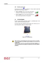
Page 32: ... ECU housing should be preferably mounted in a sheltered position on the machine with the cable output facing downwards For a proper fixing of the signal communication cables on the control unit use a wrench and tighten the cables on the relative front panel Figure 2 11 ECU positioning Both connectors should be plugged to the front panel in order to avoid water and dust penetration even if the 30 ...

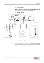
Page 33: ...n and central to the machine in order to make the cables routing easier 2 11 WIRING DIAGRAM Figure 2 12 Wiring diagram of the system with alternator The codes of the various elements are listed in the following pages The items referred as 5 alternator 8 battery and 10 battery disconnect switch are not included in the kit ...

Page 34: ...Installation PCS FS Kit 2 13 Figure 2 Wiring diagram of the system without alternator ...

Page 35: ...APHICAL CONSOLE 2 1406 601 PCS MD O 3 56C00646 PCS SDB 12 12 4 56C00651 PCS SDB 3 3 2 11 2 ECU connection Code Description Ref on wiring diagram 05R01379 ECU 18P CABLE PCS 12 05R01334 ECU PLUG 30C 20 05R01380 ECU 30P CABLE PCS 21 50A00174 HALL EFFECT SPEED SENSOR GS102301 14 05R01400 GS102301 SPEED SENSOR CABLE L 1500mm 19 05R01422 MECHANICAL SWITCH SENSOR 15 05A00173 PRESSURE SENSOR 22 ...

Page 36: ...Installation PCS FS Kit 2 15 Figure 2 14 ECU wiring diagram ...

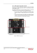
Page 37: ... corresponding to two or four cable lead through on the SDB junction boxes o The red conductors positive of the 05R01372 and or 05R01373 cables should be connected to the Wago spring terminals of the corresponding dial o The black conductors negative of the 05R01372 and or 05R01373 cabling should be connected to the Wago spring terminals in the area indicated by the black rectangle shown in the fo...

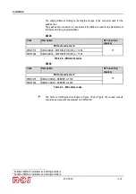
Page 38: ...CABLE L 2000 11 05R01349 BAT SDB CABLE L 1500 05R01313 B SDB CABLE L 1600 9 05R01350 B SDB CABLE L 2000 05R01333 PE BRAID FLAT 50MM 2 M10 17 05R01386 BATTERY DISCONNECT CABLE 11B 04C00142 BATTERY FUSE 125A 23 14A00073 BATTERY DOUBLE POLE 24 14A00072 BATTERY INSULATORS BORDEAUX NUTS 25 05R01385 CAN TERMINATION MOLEX SDB 26 05R01412 BAT SOCKET ISO12369 27 05R01433 SDB IF CABLE 27 The quantity and ty...

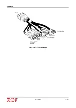
Page 39: ...the CAN socket corresponding to the dial Yellow rectangle in Figure 15 and Figure 16 The unused sockets on the distribution cables should be secured with element no 05R01381 2 9 4 ECU connection It is possible to connect the geared motors to the system using the cables indicated by the codes of the following table Connect one cabling side 18 poles black CINCH connector to the MD and the 8 poles gr...

Page 40: ...nsor2 13 05R01377 DMD CABLE DISTRIBUTOR TE L 1000 05R01384 DMD CABLE DISTRIBUTOR TE L 1300 Table 2 2 MD cables codes DMD2 Code Description Ref on wiring diagram Without seed sensor3 13 05R01475 DMD 2 CABLE SEEDER L 1700 05R01494 DMD 2 CABLE SEEDER L 2500 Table 2 3 MD cables codes The CAN on SDB yellow rectangle in Figure 15 and Figure 16 unused sockets should be secured with the element no 05R0138...

Page 41: ...contact this condition is shown by the symbol or a high reliability electromagnetic sensor e g SICK RE11 SA03 or equivalent In order to grant the required safety level Performance Level c see paragraph 1 4 7 you should foresee a safety switch having the following characteristics B10d 2 x 10e6 see note below The safety switch is not supplied with the kit as it must be chosen according to the dimens...

Page 42: ...Installation PCS FS Kit 2 21 This page is intentionally left blank ...

Page 43: ...the PCS FS to the battery or push turn the corresponding battery disconnect switch located on the machine if available Approx 4 seconds later the following screen appears on the HMI display Once the loading phase is finished the Home screen indicated by the top left icon is immediately displayed ...

Page 44: ...1 Logo and name of the active window 2 It allows to quickly return to the home screen 3 It allows to return to the previous screen 4 It allows to access the active alarms window 5 It allows to access the complete console menu 6 Selected tab 7 Not selected tabs 1 2 3 4 5 6 7 ...

Page 45: ...r manufacturer The default password is different for each manufacturer and can be changed by the manufacturer himself ROJ Service This access level is foreseen for the ROJ technical support Administrator It is the highest access level which allows to access all system functions and is reserved to the ROJ R D personnel This access level can be modified at any time by entering the Terminal menu and ...

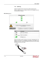
Page 46: ...on the machine to the logical position Group A Group B Group C Group D The addressing procedure requires the operator s intervention and is automatically activated on the first power up of the machine It is also possible to force this operation by opening the following window and clicking the 1 button Path Machine Tab Field Description 1 Activation button for the addressing procedure 1 ...

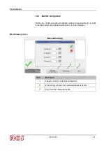
Page 47: ...ion window is opened where it is possible to read the number of motors associated to the A B C and D groups MD addressing window Field Description 1 It allows to modify the machine configuration 2 If this button is pressed the real addressing session starts 3 To exit from the addressing window 2 3 1 ...

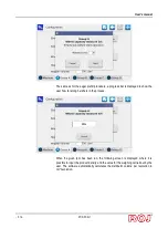
Page 48: ...ous phase is displayed MD addressing window Field Description Motor not yet addressed flashing Motor to be addressed Addressed motor Closing the protection switch see figure for the cable corresponding to the one flashing on the synopsis the logic address corresponding to the flashing icon is assigned to the motor A beep sound indicates that the motor has been correctly addressed and the icon turn...

Page 49: ...ror press the motor symbol in order to display the dialog Unaddress MD which allows to cancel the address of one a group or all motors MD addressing window Field Description Motor not yet addressed flashing Motor to be addressed Addressed motor ...

Page 50: ... window is displayed as shown below and it is possible to exit by pressing the 3 button MD addressing window Field Description 1 It allows to modify the machine configuration 2 If this button is pressed the real addressing session starts 3 To exit from the addressing window 2 3 1 ...

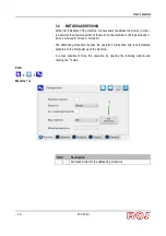
Page 51: ...ws to select the machine speed sensor Single sensor phonic wheel Double sensor phonic wheel index Radar Encoder Single sensor phonic wheel one tooth ISO11786 signal Single sensor phonic wheel fan If selected the user is asked to turn off and restart the system from the main disconnect switch battery disconnect switch 3 It enables the machine lifted machine lowered sensor with a reversed polarity 4...

Page 52: ...phonic wheel have a direct ratio 1 1 Otherwise the pulse number i should be multiplied by the up down gearing ratio ISO11786 signal The signal generated by the tractor on this interface measures the effective speed of the tractor forward movement The generated number of pulses is 130 pulses meter for a tractor speed of 1 Km h therefor the total number of pulses for the calibration will be 13000 pu...

Page 53: ...e standard one If no further external up or down gearing is applied the gear ration remains 2971 3 1 1000 The quantity of product delivered at each turn of the volumetric distributor shaft for a specific product It is possible to use the 7 function to measure the quantity delivered by the auger 4 It enables the product level sensor which is generally positioned on the hopper 5 1 3000 Total volume ...

Page 54: ...tion Press the 7 button in the configuration page to calculate by experimentation the product quantity to be delivered by the hopper through the auger The test is composed of a sequence of 5 screens that guide the user during the measuring steps For all groups the user can choose the distributor distributors that will work after the test is started or all of them The first step which is shown in t...

Page 55: ... Kit 3 13 Pressing the Start button the auger is prefilled for the given rpm Once this procedure is finished the real measurement is carried out After deciding the rpm to be run for the weighing test press the Start button ...

Page 56: ...the user how far along he she is in the process When the given rpm has been run the following screen is displayed where it is possible to input the product density and the value for the weighing carried out by the user The software automatically calculates the distributor volume per revolution in cm revolution ...

Page 57: ...sing that only one motor has been chosen it is necessary to put the bag for the weighing process under the nozzle of the selected distributor Instead if you decide to start all the motors of the machine the seed collection bag should be placed under each nozzle 3 6 SEEDING FERTILIZATION SETTINGS This window allows to set up the seeding or fertilization parameters for the 4 groups Path Machine Tab ...

Page 58: ...ulses per 100m Press the button to run the speed sensor calibration session See below 2 20 800 cm It indicates which machine is being used 3 0 16 km h It shows the maximum allowed work speed with the actual settings 4 Follow this procedure to calibrate the speed sensor on 100m 2 4 1 3 ...

Page 59: ...n and to travel this 100m section at a moderate speed 5 9 km h The number of wheel pulses will appear on the screen Once the distance has been covered it is possible to confirm the setting by clicking the 1 button Note in order to improve the precision of the absolute value for the seeding distance it is important to calibrate the seed sensor each time you change the field or if the soil condition...

Page 60: ...ange Description 1 0 2 2 Density of the product being used 2 It allows to measure the density of the product being used 3 1 1000 Amount in kg to be delivered per hectare of field 4 0 16 km h It shows the maximum allowed work speed with the actual settings 1 2 4 3 ...

Page 61: ...d and to choose a motor for the test Push the Play button to start the selected motor It is possible to stop the test or to go on with the test until all the desired simulated area has been covered As for the previously described measuring of the auger volume if you push Stop a screen will be displayed allowing to input the weighed amount for an automatic calculation of the correct product density...

Page 62: ...ine position lifted lowered of the battery and alternator status and of the row markers position get a graphical indication of the amount of seeds or fertilizers being used easily access the rows switching off function rapidly enter the effective amount contained in the hopper and get a real time estime of the residual quantity Path Synoptic display of the complete seeding fertilization system 1 2...

Page 63: ...l ha counter in relation to the actual or just finished seeding job 2 Value in km h Here you can see the real time system speed as detected by the set speed sensor 3 Row exclusion and Seeding Tab 4 Summary information Tab 5 Synoptic Tab 6 Row exclusion and Setup Tab 7 h min It shows the set time ...

Page 64: ...is working with the battery and the alternator Row markers It shows the row markers status This icon is updated in real time Machine status Machine lifted Machine lowered Indications of the seeding job Active job Inactive job Job paused When the seeding job is active the motor output shaft and the connected transmissions will rotate according to the movement of the machine as detected by the speed...

Page 65: ...this part of the chart is in background to the bar The bar colour and the background show the status of the group or the status of one of the associated motors Green group MD OK Yellow group MD switched off by pressing the tramline tramline button Rosso group MD alarm error Grey group excluded not active The number above the bar indicates the amount remaining in the hopper The quantity in kg ha to...

Page 66: ...ning amount bar it is possible to quickly load the desired amount This quantity will be added to the hopper estimated residual quantity Push the Load button to add the given quantity to the residual amount push First Load to reset the Residual field and to load the given amount ...

Page 67: ... 1 Unique progressive number assigned to the seeding job 2 Seeding job starting date and time 3 Seeding job date and time 4 Time worked 5 Tags related to the seeding job name 6 Average working speed in km h 7 Maximum working speed in km h 8 Total ha counter of the machine 9 Partial ha counter 1 2 3 4 7 6 8 9 5 ...

Page 68: ...he A group Green group MD OK Yellow group MD switched off by pressing the tramline tramline button Rosso group MD alarm error Grey group excluded not active 2 Motor status icons The icon color indicates the status of the motor associated to the B group Green group MD OK Yellow group MD switched off by pressing the tramline tramline button Rosso group MD alarm error Grey group excluded not active 3...

Page 69: ...he devices icons allow to access the diagnostics setting activation deactivation pop up windows Pop up windows of the motor associated to the group These pop up windows allow to view the status of the seeding discs related devices to check if they are enabled and to quickly access the product distribution parameters setting menu Path the same for the 4 groups Field Description 1 Indication of the ...

Page 70: ...ounters and the seeds counters are reset at the beginning of the seeding activity Press the button to resume a job which has previously been paused The partial ha counter and the seeds counter restart from the value indicated before the pause Press the Pause button to temporarily suspend the job without resetting the statistical counters related to the started job The job status indicators will tu...

Page 71: ...utton It is not possible to go on seeding The system must be disconnected from the power supply Recoverable emergency It is not possible to go on seeding The system must be disconnected from the power supply Standard error 1 bip It is possible to go on seeding but the device showing an error is not working properly Warning Yellow 1 bip Automatic after 3 seconds It is possible to go on seeding but ...

Page 72: ...User s manual 3 30 PCS FS Kit 1 Alarm acknowledgment button 2 Alarm description Alarm category 3 Active alarm which has already been acknowledged grey text 4 Alarm code ...

Page 73: ...MD 1490 Initialize timeout 1 Contact technical support 1550 Connection timeout ECU remote terminal Check connection between ECU and remote terminal 1600 Machine taxing position Machine in taxing position lifted If this is happening when machine is supposed to be seeding check cabling and machine position sensor 1610 Pressure sensor failure Check connection of pressure sensor 1611 Pressure out of r...

Page 74: ...t possible to set that combination of parameters quantity density Change the set parameters 2504 Spare parameters mismatch Not possible to set that combination of parameters quantity density Change the set parameters 2510 Seeding speed too high Reduce tractor speed 2520 Seeding job not active Start the seeding job by pressing the relative button 6000 Low voltage Check speed sensor cabling Check ba...

Page 75: ...t supplier if not solved 1xx11 Heart beat ECU missing Check CAN cable connection between ECU and DMD Check supply cable to ECU Check battery voltage 1xx12 Find rotor position error Not active on customer release 1xx13 Safety switch open Close lid or seeding element cover Check security switch 1xx14 Pwm control volt Cycle power of the system from battery disconnect Contact supplier if not solved 1x...

Page 76: ...on to a higher set value 1xx82 Deviation from theoretical investment Check seeding discs and drawer 1xx83 High number of missings Check 1xx84 Prefill not completed Verify that vacuum is correct and seeds are present in the hopper 1xx87 Seed hopper low level Verify seed hopper level ...

Page 77: ...update Where applicable you can perform the update in the following order 1 ECU 2 HMI 3 DMD The following screen allows the user to decide which part of the system should be updated Path Field Description 1 It allows to update the HMI software 2 It allows to update the ECU board software 3 It allows to update the motors software 4 It allows to update the PSB for the HMI only ROJ service 1 2 4 3 ...

Page 78: ...e just go on with the updating procedure the error is deleted after the HMI has been updated too 2 After the ECU software update it is possible that one ore more errors are displayed according to the previously installed software version as follows Configuration and setup parameters lost Invalid configuration or MD address Data checksum Invalid checksum In that case follow the procedure described ...

Page 79: ...cal parameter setup window is displayed Press the Confirm parameters button 5 Access the window Menu Terminal and press the Access button 6 Select OEM Service from the list Enter the password for the OEM service access and confirm by double clicking on the green check mark 7 Access the window Menu USB Parameters 8 Select the PAR_ date_time file If one or more files are present select the most rece...

Page 80: ...3 38 PCS FS Kit HMI software update Path Selecting the desired SW from the list and pressing the 1 button it is possible to update the HMI After the update the console shuts off automatically and the system reboots 1 ...

Page 81: ...from the list and pressing the 1 button the follow pop up window is displayed where it is possible to choose the motor and therefore the elements seeding unit fertilizers or micro granulators to be updated If you press the 2 button after the selection the selected MDs update starts 1 2 ...

Page 82: ...ted to the active seeding job and the system event log Path Field Description 1 Chart function only accessible by ROJ Service 2 Statistics related to the seeding units only active for the PCS200 3 Statistics related to the distributors included in the 4 groups 4 System events log 5 Events and statistics storage 2 3 5 4 1 ...

Page 83: ...l for ex All GroupA Path Field Description Quantity kg Quantity delivered by the distributors associated to the individual motors and Groups Gross partial ha Partial ha counter Net partial ha Partial ha counter considering only the active rows Total ha Total ha counter Event log Here you can see the system event log alarms parameters change start and stop of the seeding job etc Path 3 4 ...

Page 84: ...42 PCS FS Kit Field Description 1 Event time and date 2 Unique identifier for the seeding job 3 Event name and icon 4 Detailed event description 5 Press this button to save the Event Log you will need a USB stick 1 2 5 ...

Page 85: ... Pressing the Job archive button you can save an archive containing detailed information about the seeding jobs 3 The MD log button opens a selection window where it is possible to select the MDs for which you need to download some information This operation can take about 30 seconds for each MD 4 Press the Local event log button to display some debug information 5 The Parameters button allows you...

Page 86: ...User s manual 3 44 PCS FS Kit 3 11 TERMINAL In this window it is possible to adjust some settings related to the HMI terminal Path 1 2 3 4 6 7 5 ...

Page 87: ... case of activity the screen backlight is reduced to a minimum 6 Here it is possible to enable and set up the Home page return function delay If enabled in case of activity once the set time has expired the terminal will come back to the Home screen 7 To set up the day night backlight levels The slider controls allow to independently adjust the light levels in case of day night setup To select the...

Page 88: ...lable when the seeding job is inactive or paused Field Description 1 The selected MDs start 2 All MDs start 3 All MDs are stopped 4 Tractor speed expressed in km h 5 Motors selection window Sim Tab This tab allows to simulate the tractor speed Use this window to simulate a seeding job session without having to effectively turn the ground wheel of the machine This test mode is accessible in all the...

Page 89: ...ncreases until the target speed value is reached Target Speed following the acceleration ramp as specified in the Acceleration field If it s unselected the speed will start to decrease until the 0 value is reached following the deceleration ramp as specified in the Acceleration field 3 Current speed 4 It indicates the simulation of the top speed to be reached The value is expressed in km h 5 It in...

Page 90: ...ry 1sec with new samples 3 Update button if you press this button the samples values are refreshed Insert a USB stick into the console slot clear the Enable check box and press Refresh to store all the data on the USB drive The file name will be TORQ_ data _ time txt 4 Number of valid samples for the window in the chart 5 Torque chart window The torque value is expressed in internal representation...

Page 91: ...User s manual PCS FS Kit 3 49 This page is intentionally left blank ...

Page 92: ...nd of the equipment Prior to start the maintenance works thoroughly clean the relevant zone Do not use solvents After any maintenance task all materials having an impact on the environment such as for example lubricants dirty clothes filter elements etc must be disposed of properly in accordance with the applicable regulations Ensure that unauthorized personnel DO NOT access the working area durin...

Page 93: ...IZED PERSONNEL Operation Frequency Notes Check the safety devices operation At the beginning of each season This check can be carried out by putting the motors into service through the test functions described in paragraph 3 11 and verifying that when each MD safety switch opens the motor is stopped ...

Page 94: ...Maintenance and Troubleshooting PCS FS Kit 4 3 4 4 SPARE PARTS ...

Page 95: ...STRIBUTOR TE L 1300 05R01374 DMD CABLE SEEDER TE L 1300 05R01375 DMD CABLE SEEDER TE L 1700 05R01376 DMD CABLE SEEDER TE L 2300 05R01387 DMD CABLE SEEDER TE L 3500 50A00174 HALL EFFECT SPEED SENSOR GS102301 14 05R01422 MECHANICAL SWITCH SENSOR 15 05R01404 DMD DISTRIBUTION CABLE 3 POS 16 05R01372 DMD DISTRIBUTION CABLE 6 POS 05R01373 DMD DISTRIBUTION CABLE 7 POS 05R01333 PE BRAID FLAT 50MM 2 M10 17...

Page 96: ...Disconnect the faulty MD cable from the MD side using a wrench 3 Remove the screws which fix the motor to the support and remove the faulty motor from the seeding disc shaft or the distributor shaft 4 Fix the new motor mechanically and connect the MD cable 5 Power up the system via the battery disconnect switch 6 After the system is started an alarm 1 1801 Invalid configuration or MD address is di...

Page 97: ... Disconnect the faulty MD cables from the MD to be exchanged using a wrench 3 Remove the screws which fix the two motors and extract them from the seeding disc shaft or the distributor shaft 4 Exchange their position fix the motor in the new position and reconnect the cables 5 Power up the system via the battery disconnect switch 6 Make sure that no seeding job is active in that case press STOP 7 ...

Page 98: ...e integrity of the CAN connection towards and from the faulty MD 3 If the problem persists disconnect the system from power via the battery disconnect switch 4 Remove the fuse for the faulty MD but do not unplug the cable from the MD as it is used to keep the CAN connection towards the other motors 5 Power up the system via the battery disconnect switch 6 After the system has been started an alarm...

Page 99: ...Maintenance and Troubleshooting 4 8 PCS FS Kit This page is intentionally left blank ...

Page 100: ...Vercellone 11 13900 Biella BI Tel 39 015 84 80 111 Fax 39 015 84 80 209 E mail comm roj com www roj it REV 2 0 I 03 2016 ISO 9001 Certificates by DNV from 1996 ISO 9001 2008 Certificates in 2009 DISTRIBUTOR ...

Reviews: