background image

49

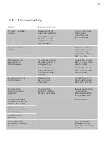
The desk stops 

and reverse during 

operation.

Make sure that 

nothing is blocking 

the table movement.

Remove the obstacle. 

If the problem 

remains replace the 

whole underframe.

Problem

Suggested correction

Only one column is 

moving.

Perform a reset. If 

there’s still only one 

column moving, 

replace the column 

that is moving.

The desk is not able 

to move.

Unplug the desk from 

the wall socket for 

roughly one minute 

and reconnect.

Make sure that all 

cabels are connected.

Connect the cables. 

Follow install 

instructions and 

perform a reset.

The desk only moves 

short distances.

Make sure that 

the desk is not 

overloaded.

Unload the desk. If 

the problem remains 

replace the ECS box.

The desk is not able 

to drive all the way up 

or all the way down.

Peform a reset.

The desk can only 

drive in one direction 

(up or down).

The desk is not 

horizontal.

680

1106

1-

A © ROL ERGO

Both columns are 

moving but at 

diff erent speeds.

It is possible to move 

the slower column by 

pulling/pushing.

It is not possible to 

move the slower 

column by pulling/

pushing.

Replace the column 

that is moving faster 

than the other.

Replace the column 

that is moving slower 

than the other.

During reset, only 

one column is moving 

downwards.

Motor or actuator 

damaged. Change 

the column that is not 

moving.

6.3 Troubleshooting

Summary of Contents for ECS+ Series

Page 1: ...USER MANUAL Series EE ECS Work 1 Colab...

Page 2: ......

Page 3: ...470 EPI BENCH 4 COLUMN 3 STAGE 650 Are manufactured in conformity with Machine Directive 2006 42 EG partly completed Machine EMC Electromagnetic Compatibility Directive 2014 30 EU and in applicable se...

Page 4: ......

Page 5: ...y information in a variety of forms Safety messages are preceded by a safety alert symbol and one of three signal words DANGER WARNING or CAUTION These safety messages are listed in order of severity...

Page 6: ......

Page 7: ...3 1 Assembly Instruction 15 3 2 System Procedure 40 4 OPERATION INSTRUCTIONS 42 4 1 Basic Functions 42 4 2 Manual Reset 44 5 MAINTENANCE REPAIRS 45 5 1 Cleaning Inspection Storage 45 5 2 User Maintena...

Page 8: ......

Page 9: ...he power supply Make sure that the cord is not damaged before usage Do not operate the stand if the power cord is damaged A damaged cord shall only be changed by authorised personnel Do not expose the...

Page 10: ...ot recommended by the manufacturer Keep the cords away from heated surfaces Never drop or insert any object into any opening Do not use outdoors Do not exceed the maximum intended load To minimize the...

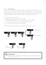
Page 11: ...under the work surface Please put this tag on desktop after assembly This tag should be placed on the table during the initial installation CAUTION The motors control unit is not designed for continu...

Page 12: ...12...

Page 13: ...rds Certificates The complete stand base is developed to harmonize with standard requirements EN 527 2 2016 Office furniture Work tables Part 2 Safety strength and durability requirements EN 1730 Furn...

Page 14: ...stem communicates internally and knows the position of each column If there are differences in column height please do a manual reset as listed in section 4 2 2 4 User Information When customer suppor...

Page 15: ...ktop and frame NOTICE Note that this assembly instruction is illustrated using generic parts Thus the visual impression of the parts can vary but the basic configuration is the same Different versions...

Page 16: ...1 Standard table top 1 2 Silent table top 2 Sliding table top 2 Columns 3 90 Connection Fixed table top 3 Columns 3 1 Standard table top 3 2 Silent table top 4 Straight Connection Fixed Sliding table...

Page 17: ...rossbar Column M8x16 x4 Sidebar Column M8x16 x4 Feet Column Plastic plug 12 Crossbar Cover for screw x4 Sidebar Washer 4 Silence pad 12 5 0 55 4 Crossbar Tabletop 4 5 20 8 Sidebar Tabletop M8 25 8 Cro...

Page 18: ...18 1 Fixed table top 2 columns Optional power supply holder Hook the holder on the crossbar before fixing the stand to the table top M8 25 8 Plastic plug 12 M8x16 x4 M8x16 x4 Cover for screw x4...

Page 19: ...ired position Observe Screws are for desktops 20 mm or thicker Loosen screws in crossbars and adjust stand width symmetric to desired position Observe Screws are for desktops 20 mm or thicker Don t co...

Page 20: ...supply cable end may vary A or B Connect the provided power supply to the corresponding outlet Observe Make sure every screw is tightened before use Turn the table around to standing position and plu...

Page 21: ...ebar Tabletop M8 25 8 Crossbar Column M8x16 x4 Sidebar Column M8x16 x4 Feet Column Plastic plug 12 Crossbar Cover for screw x4 Sidebar 68008477 ROL Ergo Plastic knob M6 22 x1 Distance x7 Glide x12 M6x...

Page 22: ...22 2 Sliding table top 2 columns M8 25 8 Plastic plug 12 M8x16 x4 M8x16 x4 Cover for screw x4...

Page 23: ...23 Plastic knob M6 22 x1 Distance x7 Glide x12 M6x16 x3 Loosen screws in crossbars and adjust stand width symmetric to desired position...

Page 24: ...g Note that the power supply cable end may vary A or B Connect the provided power supply to the corresponding outlet Observe Make sure every screw is tightened before use Turn the table around to stan...

Page 25: ...ossbar Connection Plastic plug 21 Crossbar Cover for screw x4 Sidebar Washer 6 Silence pad 20 5 0 55 10 Crossbar Tabletop 4 5 20 4 Sidebar Tabletop M8 25 11 Crossbar Column M8x16 x4 Sidebar Column Pla...

Page 26: ...r supply holder Hook the holder on the crossbar before fixing the stand to the table top M8 25 7 Plastic plug 9 M8x16 x8 M8x16 countersunk x6 Cover for screw x4 Connection 1 M8 35 1 Use for connection...

Page 27: ...0x55 x10 4 5x20 x4 5 0x55 x10 Washer x6 Silence pad x20 Loosen screws in crossbars and adjust stand width symmetric to desired position Observe Screws are for desktops 20 mm or thicker Loosen screws i...

Page 28: ...supply cable end may vary A or B Connect the provided power supply to the corresponding outlet Observe Make sure every screw is tightened before use Turn the table around to standing position and plu...

Page 29: ...Sidebar Column Crossbar Connection M8x16 x8 Feet Column Plastic plug 21 Crossbar Cover for screw x4 Sidebar Washer 6 Silence pad 20 5 0 55 8 Crossbar Tabletop 4 5 20 6 Sidebar Tabletop M8 25 16 Cross...

Page 30: ...30 4 Straight Connection Fixed table top 3 columns M8 25 8 Plastic plug 12 M8x16 x4 M8x16 x4 Cover for screw x2 Connection 1...

Page 31: ...31 M8 25 8 Plastic plug 12 M8x16 x4 M8x16 x4 Cover for screw x2 Optional power supply holder Hook the holder on the crossbar before fixing the stand to the table top...

Page 32: ...5 0x55 x8 4 5x20 x6 5 0x55 x8 Washer x6 Silence pad x20 Loosen screws in crossbars and adjust stand width symmetric to desired position Observe Screws are for desktops 20 mm or thicker Loosen screws i...

Page 33: ...supply cable end may vary A or B Connect the provided power supply to the corresponding outlet Observe Make sure every screw is tightened before use Turn the table around to standing position and plu...

Page 34: ...nch Fixed table top 4 columns 5 0 55 8 Crossbar Tabletop 4 5 20 16 Sidebar Tabletop M8 25 16 Crossbar Column M8x16 x8 Sidebar Column M8x16 x8 Feet Column Plastic plug 24 Crossbar Cover for screw x8 Si...

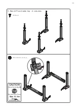
Page 35: ...35 5 Bench Fixed table top 4 columns M8x16 x8 CAUTION Use nut hex locking M8 Mounting Torque Torque Max 15 Nm DO NOT OVERTIGHTEN M8 x8 Beam Column...

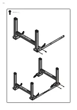
Page 36: ...36 M8 25 4...

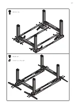
Page 37: ...37 M8 25 16 M8x16 x8 Cover for screw x8...

Page 38: ...k the holder on the crossbar before fixing the stand to the table top Loosen screws in crossbars and adjust stand width symmetric to desired position Observe Screws are for desktops 20 mm or thicker P...

Page 39: ...its diagonal it should be adjusted manually Note that the power supply cable end may vary A or B Connect the provided power supply to the corresponding outlet Observe Make sure every screw is tightene...

Page 40: ...setup To set up the desk 1 Connect the motor cables to the control unit 8 pin motor connections 2 Connect the handset to the relevant socket at the control unit ECS 3 Connect the power supply to the c...

Page 41: ...ll CAUTION When the power cord is plugged in the electrical control devices are operational NOTICE When disconnecting components such as the control box bus cable or the handset the strain relieve hoo...

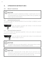
Page 42: ...o hold until desired desktop height is reached 4 1 2 Downward Desktop Movement This function enables the downward adjustment of the work surface To change its position proceed as follows Press the han...

Page 43: ...or a minimum of 5 seconds How to set memory end positions 1 Drive your desk to the level you want to store 2 Press both buttons 3 times 0 5 1 second between each pressing 3 Then press up or down to se...

Page 44: ...ST be performed A reset cycle should be made with an evenly distributed weight of approx 45 kg 100 lbs applied on the desk Perform a reset by Simultaneously pressing the up and down buttons for minimu...

Page 45: ...and damaged plugs wires Inspect control box for loose connections and damaged plugs wires The power supply and the handset is sealed and maintenance free 5 3 Repairs Check all screws and bolts after...

Page 46: ...he elevation of the desk at all times This information will remain stored even in case of power failure or if the power cable is disconnected from the power outlet 5 4 Servicing of Double Insulated Pr...

Page 47: ...47 6 APPENDIX 6 1 Dimensions leg system Series EE ECS with 650 stroke 585 650 STROKE 1235 650 STROKE 586 650 STROKE 1236 650 STROKE 585 650 STROKE 1236 650 STROKE...

Page 48: ...48 6 2 Dimensions leg system Series EE ECS with 470 stroke 647 470 STROKE 1117 470 STROKE 1137 470 STROKE 647 470 STROKE 667 470 STROKE 1137 470 STROKE...

Page 49: ...e desk only moves short distances Make sure that the desk is not overloaded Unload the desk If the problem remains replace the ECS box The desk is not able to drive all the way up or all the way down...

Reviews: