WARNING
PAGE 1
5910200_Rev A • Questions? (800) 239-6992 • RolaProducts.com
PAGE 1
59401_IN_Rev A • Questions? (800) 234-6992 • RolaProducts.com
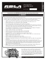
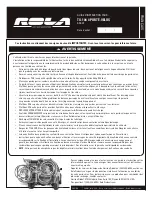
These instructions contain IMPORTANT safety information. Please read and keep for future reference.
The user must read and understand these Instruction Sheets and the Warranty.
Installation is the end user’s responsibility and beyond Horizon Global’s control. Therefore, Horizon Global exclusively limits its Warranty to
the repair or replacement of a defective product. Damage to your vehicle, your cargo or any person or property is excluded.
• Your bike carrier must be inspected for signs of wear, corrosion and fatigue before each use. DO NOT use if bent or deformed.
• Make sure your bike carrier is secure before every trip. Check at each stop to ensure your bike carrier is secure.
• DO NOT exceed your bike carrier’s rated capacity. The capacity is 100lbs (45kg).
• Do not attempt to drill, weld, or modify your bike carrier or any of the system components.
• This carrier is designed for typical use and applications (on paved or smooth gravel roads). Do not use this carrier on a vehicle that
will be driven on rough roads, or where the carrier (and bikes) will be subjected to significant or constant jarring and/or shock, or any
vehicle with very stiff springs that will transfer the load shocks directly to the carrier and the bikes.
• The recommended minimum ground clearance is 14”. This may not be sufficient ground clearance depending on the application.
Damage to bicycles or carrier due to ground clearance problems are not covered by warranty.
• Bike tires should be at least 6 inches away from exhaust pipe.
• DO NOT use this bike carrier with recreational vehicles, trailers or in off road situations.
• DO NOT use your bike carrier for purposes other than those for which it was designed.
• REDUCE YOUR SPEED. Your vehicle can handle differently when transporting cargo on the trunk.
• FREQUENTLY check your bike carrier and that the bikes are secure. Bikes can shift or your bike carrier can loosen during travel.
Readjust as needed. If movement continues, stop use.
• ALWAYS unload bikes before removing your bike carrier from hitch.
• Check local and state laws governing projection of objects beyond the perimeter of a vehicle.
• ALWAYS obey all posted speed limits and be aware of traffic conditions. Adapt your speed to the conditions of the road and the load
being carried.
• The proper attachment of this product in accordance with the enclosed instructions is critical to its proper performance. See
instructions for proper attachment, proper usage, and important safety messages. Horizon Global has no control over, or responsibility
for, the attachment or the installation. Horizon Global is NOT responsible nor will it be held liable for any damage resulting from its
attachment or improper use. Horizon Global shall not be liable for any claims of any kind greater than the purchase price of the
product. Warranty information available upon request.
• NOTICE
: Your bike carrier will not prevent property damage that may result from improper loading, securing, or driving. Insure all
locks are locked, that all pins are secured, and that all straps are properly attached prior to moving the vehicle.
INSTRUCTION GUIDE FOR:
TX-104 Bike Carrier
59401
Date of Purchase:
/
/
ENGLISH
Review all Warnings, Instructions, and Warranty information carefully.
Failure to follow these warnings and instructions will void the Warranty.
Call Horizon Global Technical Services at (800) 234-6992 or go to RolaProducts.
com, if you have any questions regarding the use or the limits of your bike
carrier. For assistance with this product or to order replacement parts, please
contact Horizon Global, 47912 Halyard Drive Suite 100, Plymouth, MI 48170
Questions? (800) 234-6992 • RolaProducts.com

