background image

PAGE 5

59401_IN_Rev A • Questions? (800) 234-6992 • RolaProducts.com

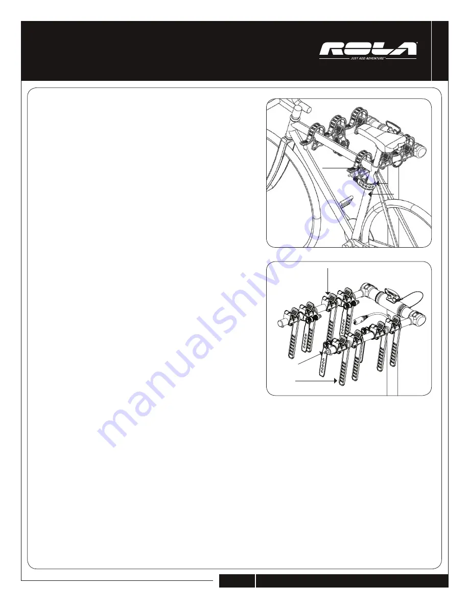
An#-­‐Sway   Cradle   

FIG   5   

ENGLISH

PROPER USAGE

5

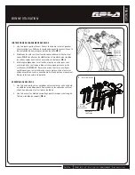
BIKE LOADING INSTRUCTIONS

1.  Once carrier is secured to vehicle, bikes can be  loaded onto the rack. 

Alternate each bike, with the anti-sway cradle being closest to the 

seat tube. 

FIG 5

.

2.  Secure the bikes by pulling the straps over the top of the bike frame. 

FIG 5

. The anti-sway straps wrap around the seat tube and prevent the 

bike from swaying. 

FIG 6

.

3.  Check the straps periodically, and after stopping, to ensure that they 

are still tight and that someone has not released them.  

NOTE

: Ensure all locks are locked, that all pins are secured, and that 

all straps are properly attached prior to moving the vehicle. Failure to 

do so will void warranty.

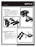
LOCKING  BIKES

1.  Once carrier and bikes are secured to vehicle, lock can be routed 

between bike frames and secured to the stud on the right arm. 

2.  Once unlocked, lock cable can be pushed back into the support tube 

for storage. 

FIG 6

.

6

Anti-Sway Strap

Anti-Sway 

Cradle

Lock

Lock Stud

Anti-Sway  

Straps

Anti-Sway Cradle

Seat Tube

Summary of Contents for TX-104

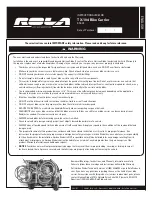
Page 1: ...for which it was designed REDUCE YOUR SPEED Your vehicle can handle differently when transporting cargo on the trunk FREQUENTLY check your bike carrier and that the bikes are secure Bikes can shift o...

Page 2: ...for assembly 1 3 4 wrench wrench included J PART DESCRIPTION QTY PART DESCRIPTION QTY A Main Support Tube 1 F 1 2 13x3 1 2 Hex Bolt 1 B Collar Bracket 1 G 1 2 13 Lock Nut 1 C Bushing 2 H 5 8 Anti Rat...

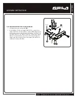
Page 3: ...support tube A Then connect main support tube A to collar bracket B as shown in FIG 1 Align bushing hole with lower hole in collar bracket and install one 1 13x3 lg hex bolt F two 2 flat washers D and...

Page 4: ...Insert handle into the holes and push downward to secure FIG 3 3 Receiver H I Handle D Align holes in tube 4 FOLDING CARRIER FOR HATCH TRUNK CLEARANCE 1 Securely hold main support tube A and remove ba...

Page 5: ...from swaying FIG 6 3 Check the straps periodically and after stopping to ensure that they are still tight and that someone has not released them NOTE Ensure all locks are locked that all pins are secu...

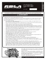
Page 6: ...los pour des finalit s autres que celles pour lesquelles il a t con u R DUISEZ VOTRE VITESSE Votre v hicule peut se comporter diff remment quand il est charg Contr lez FR QUEMMENT votre porte v los et...

Page 7: ...3 4 1 1 16 incluse J PI CE DESCRIPTION QT PI CE DESCRIPTION QT A Tube de support principal 1 F Boulon 6 pans 1 2 13x3 1 2 1 B Support de collier 1 G Contre crou 1 2 13 1 C Bague 2 H 5 8 Broche anti c...

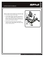
Page 8: ...collier B comme c est montr en FIG 1 Alignez le trou de bague avec le trou du bas dans le support de collier et installez un 1 boulon 6 pans de 1 2 13x3 1 2 F deux 2 jeux de rondelles plates de 1 2 D...

Page 9: ...tube FIG 3 3 Ins rez la poign e dans les trous et poussez la vers le bas pour fixer FIG 3 3 R cepteur H I Poign e D Alignez les trous dans le tube 4 PLIAGE DU PORTE V LOS POUR D GAGER LA PORTE ARRI RE...

Page 10: ...s un arr t pour vous assurer qu elles sont toujours bien serr es ou que personne ne les a rel ch es REMARQUE Assurez vous que tous les verrouillages sont bloqu s que toutes les broches sont en place...

Page 11: ...os para los que se lo dise REDUZCA LA VELOCIDAD Su veh culo puede maniobrar de manera diferente cuando transporta bicicletas Revise CON FRECUENCIA el soporte para bicicletas y verifique que las bicicl...

Page 12: ...1 Llave de 3 4 incluida J PIEZA DESCRIPCI N CANT PIEZA DESCRIPCI N CANT A Tubo de apoyo principal 1 F Perno hexagonal 1 2 13 x 3 1 2 1 B Soporte de collar 1 G Contratuerca 1 2 13 1 C Buje 2 H Pasador...

Page 13: ...A al soporte de collar B como se muestra en la FIG 1 Alinee el agujero del buje con el agujero inferior del soporte de collar e instale un 1 perno hexagonal de 13 x 3 long F dos 2 arandelas planas de...

Page 14: ...o se alineen FIG 3 3 Inserte la manija en los agujeros y empuje hacia abajo para asegurarla FIG 3 3 Receptor H I Manija D Alinee los agujeros en el tubo 4 PLEGADO DEL SOPORTE PARA DESPEJE DE PUERTA TR...

Page 15: ...dicamente y despu s de detenerse para asegurarse de que est n todav a tensas y que nadie las haya soltado NOTA Aseg rese de que todas las trabas est n en posici n de bloqueo que todos los pasadores es...

Reviews: