16
Mar. 2008
GT-10
System Update Error Messages
If the update fails, a message like the ones shown below is displayed.
Check Sum Error
A problem was found in the checksum value for the received Standard MIDI
file (SMF).
Receive Error
The received SMF may have a problem, the MIDI transmission may have been
interrupted, or the MIDI cable may be disconnected or have a broken wire.
Flash Write Error
Writing to the flash ROM failed. The peripheral circuitry for the flash ROM
may be defective, or the MIDI cable may be disconnected or have a broken
wire.
Also, if two asterisks (“*”) are displayed while data is being received, it means
that receipt of MIDI data has failed.
* Stopping partway through and resending also causes two asterisks to be
displayed, but this does not signify a problem.
Test Mode
Items Required
• Expression pedal (Roland EV-5) x 1
• MIDI cable x 1
• USB cable x 1
• Cable with a 1/4-inch phone plug x 1 (having a 33-ohm resistor [1/4 W
or more] connected between L channel and ground and between R
channel and ground)
• DIGITAL IN-compatible device x 1 (device that converts digital audio
signal to analog audio signals: Roland DA-400 or the like)
• Digital audio cable (coaxial) x 1
• Computer x 1
• Headphones x 1 set
• Oscilloscope x 1
• Monitor speaker x 2
• Noise meter x 1
• Tester x 1
• 47-k ohm plug x 1 (having a 47-k ohm resistor connected between the
signal line and ground, and having a metal cover [shielding] over the
area where the resistor is mounted)
• Dummy plug x 1 (open plug)
• Push/pull force gauge (capable of measurement from 100 g to 1 kg and
from 10 kg to 50 kg)
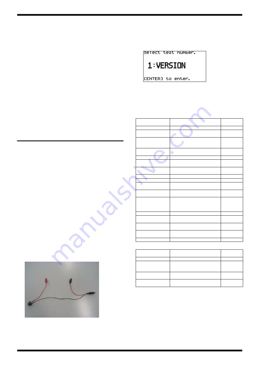
• Cable for measurement of DC IN current consumption
fig.check-cable.eps
* Before starting, on the computer, install and set up the folder containing the
dedicated USB driver for the GT-10 (GT-10 USB Driver) and the dedicated USB
checking software for the GT-10 (USBCheck.exe, the DLL, the settings file, and
the like). The GT-10 USB Driver and USBCheck.exe are obtained via Service
Network. USBCheck.exe runs only under Windows XP.
Entering the Test Mode/Selecting Test
Items
1.
Hold down [OUTPUT SELECT] and [SYSTEM] and switch on the power.
* Continue holding down the buttons until a screen like the one shown below
appears.
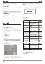
fig.1version.eps
2.
Turn the dial to select the test item, then press [CATEGORY/ENTER].
Test Items
Quitting the Test Mode
Switch off the power.
Test items in the Test Mode
Screen display
Test description
Page where
described
1. VERSION
2. DEVICE
Testing of the Peripheral ICs for
the CPU and for the DSP
3. LCD/ENC
Testing Covering LCD Contrast,
Missing LCD Dots, and Encoder
Operation
4. SW/LED
Testing of Operation Switches
and LEDs
5. OUTPUT LEV
6. PARAM KNOB
Testing of the PARAMETER Con-
trols
7. INT EXP
Testing of the Expression Pedal
and Pedal-calibration Settings
8. EXT EXP
Testing of the External Pedal Jack
9. MIDI
10. AMP CTRL
Testing of the AMP CONTROL
Jack
11. USB&D.OUT
Testing of the USB Circuitry and
DIGITAL OUT Circuitry
12. OUTPUT&MUTE
13. INPUT
Testing of the INPUT Circuitry
14. RETURN
Testing of the RETURN Circuitry
and the RETURN Jack Switch
15. INPUT NOISE
Testing of Residual Noise and
Shock at the Respective Outputs
16. LOOP NOISE
Testing of the SEND/RETURN
Connection and RETURN Shock
17. FACT RESET
Test items outside the Test Mode
Test name
Test description
Page where
described
Short check
Testing of AMP CTRL Insulation
EXP pedal operation-
load test
Testing of Load at Which Move-
ment of the Expression Pedal
Starts
Muting and Play
Mode test
Testing of Muting Circuitry and
Verification of Product Startup
Current-consump-
tion Test
Summary of Contents for Boss GT-10
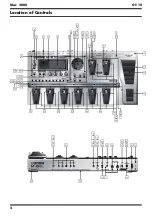
Page 4: ...4 Mar 2008 GT 10 Location of Controls fig panel GT 10 eps...
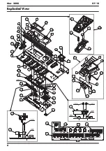
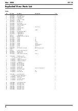
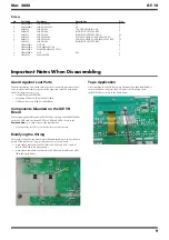
Page 6: ...6 Mar 2008 GT 10 Exploded View fig bunkai eps L...
Page 7: ...7 Mar 2008 GT 10 fig bunkai eps R...
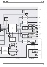
Page 11: ...11 Mar 2008 GT 10 fig block wiring eps R...
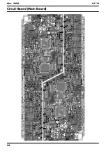
Page 24: ...24 Mar 2008 GT 10 Circuit Board Main Board fig b main 1 eps...
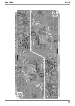
Page 25: ...25 Mar 2008 GT 10 fig b main 2 eps...
Page 26: ...26 Mar 2008 GT 10 Circuit Diagram Main Board 1 5 fig d main 1 eps L...
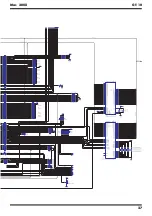
Page 27: ...27 Mar 2008 GT 10 fig d main 1 eps R...
Page 28: ...28 Mar 2008 GT 10 Circuit Diagram Main Board 2 5 fig d main 2 eps L...
Page 29: ...29 Mar 2008 GT 10 fig d main 2 eps R...
Page 30: ...30 Mar 2008 GT 10 Circuit Diagram Main Board 3 5 fig d main 3 e eps L...
Page 32: ...32 Mar 2008 GT 10 Circuit Diagram Main Board 4 5 fig d main 4 eps L...
Page 33: ...33 Mar 2008 GT 10 fig d main 4 eps R...
Page 34: ...34 Mar 2008 GT 10 Circuit Diagram Main Board 5 5 fig d main 5 eps L...
Page 35: ...35 Mar 2008 GT 10 fig d main 5 eps R...
Page 36: ...36 Mar 2008 GT 10 Circuit Board SW VR Pedal Bank ENC EXP Board fig b sw 1 eps...
Page 37: ...37 Mar 2008 GT 10 fig b sw 2 eps...
Page 38: ...38 Mar 2008 GT 10 Circuit Diagram SW VR Board fig d sw vr eps L...
Page 39: ...39 Mar 2008 GT 10 fig d sw vr eps R...
Page 40: ...40 Mar 2008 GT 10 Circuit Diagram Pedal Board fig d pedal eps L...
Page 41: ...41 Mar 2008 GT 10 fig d pedal eps R...
Page 44: ...MEMO Mar 2008 GT 10...


