9
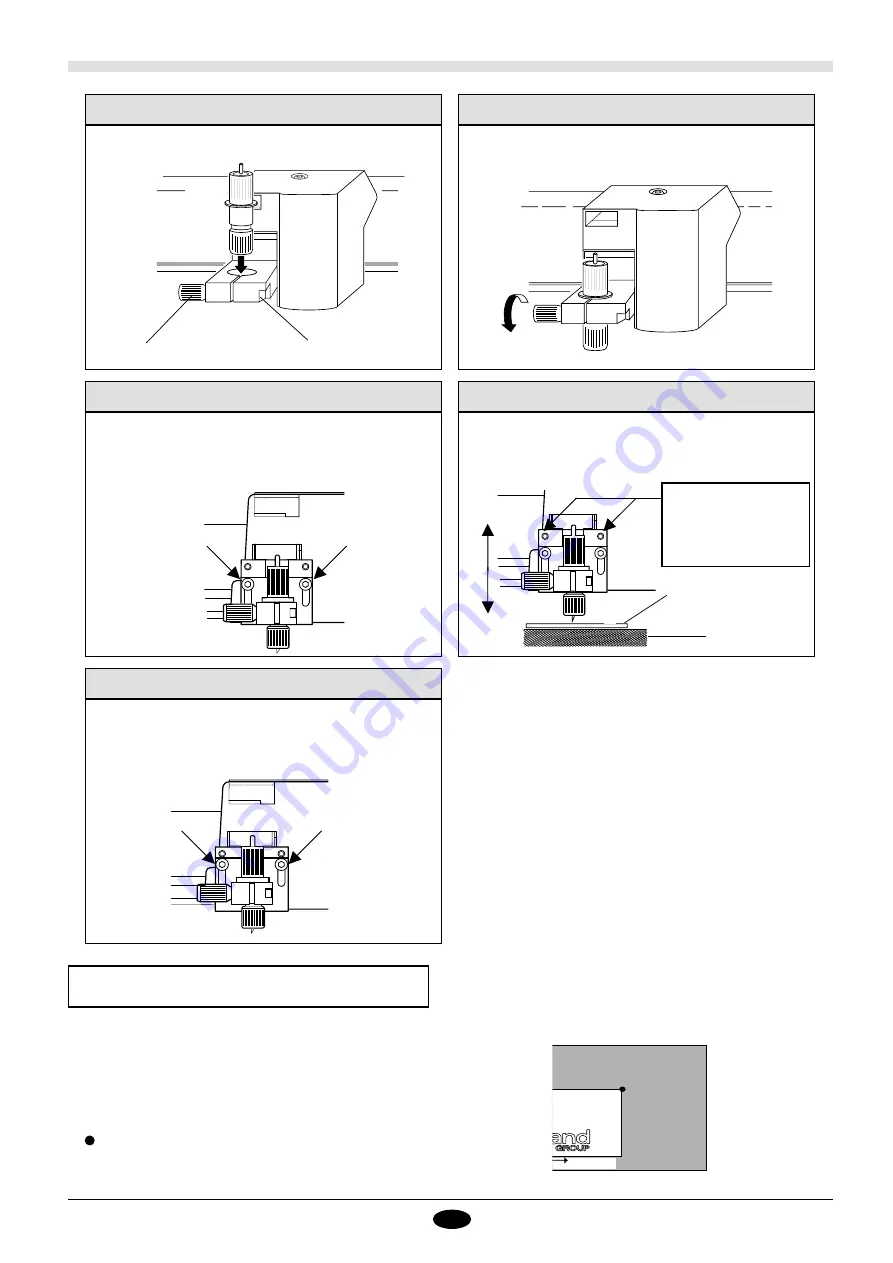
Firmly tighten down the tool mounting screw so that the
blade holder does not move.
Securing the Blade Holder in Place
Loosen the tool setscrew on the tool holder and insert the
blade holder.
Mounting a Blade Holder
Tool setscrew
Tool holder
Adjusting the Height of the Tool Holder 1
When loading a thick material, adjust the height so that the
material does not catch on the blade holder. Use the hex
wrench included with the machine to loosen the screws
shown in the figure.
Adjusting the Height of the Tool Holder 2
If the thickness of the
material is 8 mm
(5/16") or more, use
the upper hole.
The tool holder can be shifted up or down. Adjust it to a
height that allows the tool gap gauge to pass with no
resistance.
Blade gap gauge
Material
Adjusting the Height of the Tool Holder 3
After positioning the blade holder, tighten the screws with
the hex wrench.
7. Setting the Cutting Area
UR
X
The cutting area is determined by setting the LL and UR for the
material on the cutting table. Be sure to make this setting before
performing a cut. Also note that the first time you use this
product, the LL is set to the bottom left corner of the cutting
table, and the UR is set to the upper right corner of the cutting
table.
When LL and UR have been set respectively as the lower-left
and the upper-right, the X axis is horizontal (left-right), and
the Y axis is vertical.
LL is lower left and UR is upper right
Summary of Contents for CAMM-1 PNC-1610
Page 41: ...R12 980109 ...


