background image

●この機器を使用する前に、以下の指示と取扱
説明書をよく読んでください。

.............................................................................................................

●この機器を分解したり、改造したりしないで
ください。

.............................................................................................................

●修理/部品の交換などで、取扱説明書に書か
れていないことは、絶対にしないでください。
必ずお買い上げ店またはローランド・サービス
に相談してください。

.............................................................................................................

●次のような場所での使用や保存はしないでく
ださい。
○温度が極端に高い場所(直射日光の当たる場
所、暖房機器の近く、発熱する機器の上など)
○水気の近く(風呂場、洗面台、濡れた床など)
や湿度の高い場所
○ホコリの多い場所
○振動の多い場所

.............................................................................................................

●この機器を、ぐらついた台の上や傾いた場所
に設置しないでください。必ず安定した水平な
場所に設置してください。

.............................................................................................................

警告

警告

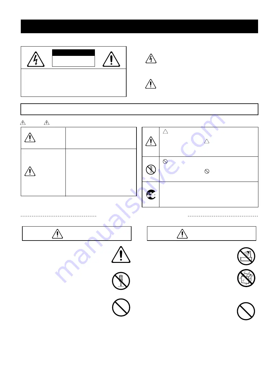
安全上のご注意

火災・感電・傷害を防止するには

このマークは、注意喚起シンボルです。取扱説明書
などに、一般的な注意、警告、危険の説明が記載さ
れていることを表わしています。

このマークは、機器の内部に絶縁されていない「危
険な電圧」が存在し、感電の危険があることを警
告しています。

マークについて

この機器に表示されているマークには、次のような意味があります。

注意:

感電防止のため、パネルやカバーを外さないでください。
この機器の内部には、お客様が修理/交換できる部品
はありません。
修理は、お買い上げ店またはローランド・サービスに
依頼してください。

注意

感電の恐れあり

キャビネットをあけるな

以下の指示を必ず守ってください

図記号の例

取扱いを誤った場合に、使用者が
傷害を負う危険が想定される場合
および物的損害のみの発生が想定
される内容を表わしています。

※物的損害とは、家屋・家財およ

び家畜・ペットにかかわる拡大
損害を表わしています。

取扱いを誤った場合に、使用者が
死亡または重傷を負う可能性が想
定される内容を表わしています。

 は、強制(必ずすること)を表わしています。

具体的な強制内容は、

 の中に描かれています。

左図の場合は、「電源プラグをコンセントから抜
くこと」を表わしています。

警告

注意

注意の意味について

警告と

  は、注意(危険、警告を含む)を表わしていま
す。
具体的な注意内容は、  の中に描かれています。
左図の場合は、「一般的な注意、警告、危険」を
表わしています。

  は、禁止(してはいけないこと)を表わしてい
ます。
具体的な禁止内容は、  の中に描かれています。
左図の場合は、「分解禁止」を表わしています。

2

Summary of Contents for CPM-300

Page 1: ...300 150W 150W 4 6 0Kg 1 2 1 3 PA 6 2 10 SENS PA PC DC ECOS Efficiency Control Operation System ECOS Efficiency Control Operation System 1 2 1 3 POWERED MIXER CPM 300 P 2 3 P 4 1998 01677301 99 10 C2...

Page 2: ...2...

Page 3: ...AC100V P 9 3...

Page 4: ...2 3 6 4...

Page 5: ...2 4 6 6 6 7 8 9 9 10 10 11 12 12 12 12 13 13 14 14 14 14 15 15 15 16 16 16 17 18 20 21 22 23 24 25 5...

Page 6: ...1 6 7 8 9 10 1 SENS PEAK 6 1 6 4 dBm 60 dBm 7 8 9 10 4 dBm 20 dBm 2 EQ 0 P 12 3 SEND SEND 9 0 P 22 4 PAN L R L R 5 BAL L R L R 6 PEAK 6dB PEAK EQ 10 11 12 13 5 8 7 9 1 2 3 4 6 6...

Page 7: ...8 DSP PROCESSING DIGITAL REVERB P 13 ANTI FEEDBACK P 14 9 SEND RETURN SEND SEND 3 DSP PROCESSING 8 SEND P 8 0 RTN RETURN P 8 0 10 MIXER OUT 0 4dBm P 9 100W 8 AMP IN P 8 P 11 11 POWER ON 12 PHONES P 2...

Page 8: ...XLR TRS 2 6 7 8 9 10 RCA 9 10 RCA 15 RETURN P 11 L 16 SEND P 11 17 REC OUT RCA P 22 10dBm 18 MIXER OUT AMP IN P 11 AMP IN P 11 MIXER OUT 19 PHONES 1 2 3 1 GND 2 HOT 3 GND GND SLEEVE HOT TIP GND RING G...

Page 9: ...1 POWER ON OFF 2 2 4 8 8 4 6 8 3 4 6 6 3 4 4 2 PC CPM 300 4 PC 4 CPM 300 PC 1 2 9...

Page 10: ...AX MIN MAX MIN REVERB LEVEL VARIATION FLAT BANK L SYNTH STRINGS INTERNAL CONTROL HARPSI ORGAN CLAVI RHODES E PIANO E GRAND MKS 20 GRAND 1 GRAND 2 BASS PERCUSSION 5 6 3 4 1 2 C D B 7 8 SETUP MEMORY NUM...

Page 11: ...SEND RETURN RETURN L MIXER OUT AMP IN AMP IN MIXER OUT AMP IN MIXER OUT AMP IN MIXER OUT CPM 300 AMP IN AMP IN MIXER OUT CPM 300 11...

Page 12: ...SENS EQ 0 12 PAN BAL 12 SEND RETURN CD CPM 300 ON P 17 1 SENS PEAK 2 0 3 PEAK SENS 4 PAN BAL EQ EQ 0 HIGH 12kHz 15dB 15dB LOW 80Hz 15dB 15dB CD P 13 P 24 12...

Page 13: ...CPM 300 ECHO HALL STAGE ROOM 1 2 SEND 0 12 3 SEND 4 LEVEL 5 TIME 6 SENS SEND P 14 TIME LEVEL SEND 13...

Page 14: ...CPM 300 2 1 ON 2 ON OFF ON ON OFF 3 1 6 SENS 4 AUTO SET AUTO SET 5 AUTO SET AUTO SET AUTO SET AUTO SET AUTO SET AUTO SET ON OFF OFF ON OFF ON OFF ON 14 ON OFF ON OFF AUTO SET AUTO SET...

Page 15: ...1 6 PHONES PHONES AUTO SET AUTO SET CPM 300 ON OFF ON 1 6 1 6 SEND SEND LEVEL 1 6 SEND SEND LEVEL ON OFF ON 1 6 CD 7 8 9 10 CD 7 8 9 10 1 6 1 6 7 8 9 10 OUT PUT 15...

Page 16: ...CPM 300 CPM 300 8 6 ON OFF ON 2 12dB 6dB AUTO SET 6dB 6 12dB 16...

Page 17: ...CPM 300 CPM 300 1 100 2 DC DC DC 3 ON 17...

Page 18: ...IN MIXER OUT AMP IN MIXER OUT AMP IN P 11 1 HOT CPM 300 1 GND 1 XLR TRS 4 PC 4 PC P 9 4 P 17 DC DC DC DC P 17 SEND SEND DIGITAL REVERB LEVEL 1 2 3 1 GND 2 HOT 3 GND GND SLEEVE HOT TIP GND RING GND SL...

Page 19: ...ON OFF OFF AUTO SET ON OFF OFF ON OFF ON OFF ON 1 6 AUTO SET AUTO SET CPM 300 1 6 1 6 SEND SEND LEVEL 1 6 SEND SEND LEVEL 1 6 ON OFF ON 1 6 CD 7 8 9 10 REC OUT RCA 19...

Page 20: ...ominal all sens min 49 dBm master fader max all channel fader nominal all sens max 70 dB 1 kHz 60 dB 1 kHz L R HIGH EQ 15 dB 12 kHz LOW EQ 15 dB 80 Hz 48 kHz 24 2 100 W 2 8 1 kHz 0 1 THD 150 W 2 4 1 k...

Page 21: ...7 5 mV 4 dBm 1 23 V 10 dBm 245 mV 40 dBm 7 8 mV 24 dBm 12 3 V 40 dBm 7 8 mV 24 dBm 12 3 V 0 dBm 775 mV 24 dBm 12 3 V 6 3 k 6 3 k 10 dBm 2 45 V 8 3 k 12 k STEREO 6 k MONO 1 k 1 k 1 k 2 k STEREO 1 k MON...

Page 22: ...IGH LOW BALANCE RETURN RETURN 10dBm POWER AMP 150W 4 AMP IN L 4dBm MIXER OUT L 4dBm MASTER FADER L POWER AMP 150W 4 AMP IN R 4dBm MIXER OUT R 4dBm MASTER FADER R METER DIGITAL REVERB R L MONO CH 7 10...

Page 23: ...23 360 11 131 25 64 307 4...

Page 24: ...24...

Page 25: ...ON OFF ANTI FEEDBACK 14 15 16 PAN 6 12 PC 9 PEAK 7 12 PHONES 8 10 PHONES 7 15 POWER 7 POWER 9 REC OUT 8 10 RETURN 8 10 11 ROOM DIGITAL REVERB 13 RTN 7 SEND 8 10 11 SEND RETURN 8 10 11 SEND 6 13 15 SE...

Page 26: ...determined by turning the equipment off and on the user is encouraged to try to correct the interference by one or more of the following measures Reorient or relocate the receiving antenna Increase th...

Page 27: ...Power Amp Section The mixer s amplifier is equipped with a limiter circuit providing protection against the clipping that can cause distor tion and blown speakers Protection Circuits for Added Reliabi...

Page 28: ...ould be taken so that objects do not fall and liquids are not spilled into the enclosure through openings The product should be serviced by qualified service personnel when The power supply cord or th...

Page 29: ...be placed so they are out of the reach of children Never climb on top of nor place heavy objects on the unit Never handle the power cord or its plug with wet hands when plugging into or unplugging fr...

Page 30: ...unit with a soft dry cloth or one that has been slightly dampened with water To remove stubborn dirt use a cloth impregnated with a mild non abrasive detergent Afterwards be sure to wipe the unit thor...

Page 31: ...Reverberation to the Sound Digital Reverb 13 Operating the Digital Reverb 13 Eliminating Feedback Anti Feedback Function 14 How to Avoid Feedback 14 Using the CPM 300 s Anti Feedback Function 14 Proce...

Page 32: ...ction SEND knob 9 Output is normal when the knob is set to the 0 position This signal is output after passing through the channel fader post fader Refer to the Block Diagram p 22 4 PAN Panpot Knob Thi...

Page 33: ...set to the 0 position RTN Return Knob This adjusts the input signal from the connector section s RETURN jack p 8 Input is normal when the knob is set to the 0 position 10 MASTER LEVEL Meter This meter...

Page 34: ...ct device is input here p 11 This also can be used as an auxiliary input Mono input is possible by connecting only to the L input 16 SEND Jack Standard Phone Type This is used for connecting external...

Page 35: ...ecting multiple speakers in parallel Ex 8 ohms 8 ohms 4 ohms YES 6 ohms 8 ohms 3 4 ohms NO 6 ohms 6 ohms 3 ohms NO 4 ohms 4 ohms 2 ohms NO Although the CPM 300 is protected from damage by the PC Contr...

Page 36: ...ob positions and other settings Electronic Musical Instruments XP 60 RD 500 etc Recording Equipment Tape Recorder DAT etc Equalizer etc CD Player Stereo Headphones RH 120 etc Effects Processor SE 70 e...

Page 37: ...tion to their use in connecting devices such as equalizers and compressor limiters the MIXER OUT AMP IN jacks can also be used in the following circumstances When volume levels greater than the CPM 30...

Page 38: ...is too hot strong 4 Set the sound image for each channel with the PAN and BAL knobs The black range along the channel fader and MASTER fader markings indicate the normal range within which you can ope...

Page 39: ...l Reverb 1 Select the Reverb mode 2 Set the SEND knobs to 0 12 o clock position on any channel on which reverb is to be added to the sound 3 Rotate the SEND knob Master Section to adjust the level of...

Page 40: ...ted feedback during performances Procedure for Operating the Auto Adjust Function 1 Set up microphones at the positions they will be used then switch them on 2 Switch the ON OFF switch to ON ON OFF In...

Page 41: ...in progress Common Notes about the Auto Adjust and Dynamic Adjust Functions In some cases due to certain device conditions and settings feedback may not be completely eliminated The Anti Feedback fun...

Page 42: ...Function which operates continuously whenever the Anti Feedback ON OFF switch is set to ON except when Auto Adjust is in progress It monitors the sound for feedback during performances and elim inate...

Page 43: ...interior temperature falls if the overheating pro tection circuit is activated again check to make sure that the operating environment and connected output speakers conform to the CPM 300 s specifica...

Page 44: ...o protect the speakers and the sound may be cut off or distorted Check to make sure the speaker cables are not shorted and that the speaker impedance is not less than 4 ohms PC Limiter Circuit p 9 The...

Page 45: ...6 that has been routed through the internal digital reverb by means of the channel SEND knobs and MASTER Section s SEND knob When Anti Feedback function cannot eliminate feedback while the internal di...

Page 46: ...lving type Digital Reverb Sampling Frequency 48 kHz Internal Signal Processing 24 bits 2 Power Amplifier Section Rated Output 100 W x 2 Stereo 8 load 1 kHz 0 1 or less THD 150 W x 2 Stereo 4 load 1 kH...

Page 47: ...ut Impedance Recommended Source Impedance Type of Connectors Input Socket AMP IN 4 dBm 1 23 V 11 k Less than 2 k XLR 3 31 Unbalanced 1 4 TRS PHONE Unbalanced 1 4 PHONE 1 4 PHONE RCA PHONO CH 9 10 1 4...

Page 48: ...SENS HIGH LOW BALANCE RETURN RETURN 10dBm POWER AMP 150W 4 AMP IN L 4dBm MIXER OUT L 4dBm MASTER FADER L POWER AMP 150W 4 AMP IN R 4dBm MIXER OUT R 4dBm MASTER FADER R METER DIGITAL REVERB R L MONO C...

Page 49: ...23 Dimensions 14 13 16 7 16 5 3 16 1 2 9 16 12 1 8 3 16...

Page 50: ...24 Blank User Settings Chart Copy this then use it to jot down your settings...

Page 51: ...REVERB 13 LOW EQ 12 MASTER Fader 7 12 MASTER LEVEL Meter 7 MIXER OUT AMP IN Jack 8 10 11 Muting Circuit 17 ON OFF Indicator ANTI FEEDBACK 14 ON OFF Switch ANTI FEEDBACK 14 15 16 OUTPUT AMP IN 8 10 11...

Page 52: ...Center Khaled Ibn Al Walid St P O Box 13520 Damascus SYRIA TEL 011 2235 384 TURKEY Barkat Muzik aletleri ithalat ve ihracat limited ireketi Siraselviler Cad Billurcu Sok Mucadelle Cikmeze No 11 13 Ta...

Reviews: