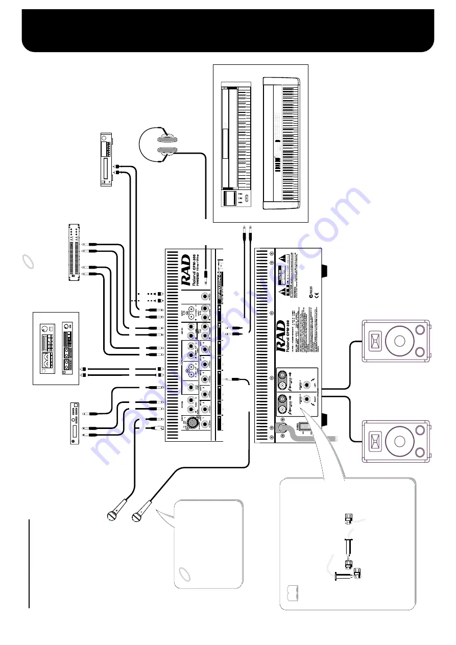
Connections
10
MODULA
T
ION
BENDER
FUNC
CONTR
O
L
T
RANSPOSE
ZONE
TX
C
H
DEPTH
TIME
CONTR
OL
RX
C
H
TRANSPOSE
ZONE
KE
Y T
O
UCH
TREMOLO
AT
TA
C
K
INDICA
T
O
R
VELO SENSE
DECA
Y
LOCAL
BEND DO
WN
RELEASE
BU
L
K
BEND UP
BRIGHT
ENTER
A/B
0
7
4
1
8
5
2
9
6
3
DETUNE PITCH
SPLIT
BANK M
P
GM C
TRANSPOSE
DEC
INC
CHOR
US
LO
WER
DU
AL
SPLIT
UPPER
EQ
U
A
LIZER
T
X
CONTR
O
L
MA
X
MIN
MA
X
MIN
MA
X
MIN
REVERB
LEVEL
V
ARIA
T
ION
FL
A
T
BANK L
SYNTH
STRINGS
INTERNAL CONTR
OL
HARPSI
ORGAN
CL
A
V
I/
RHODES
E.PIANO
E.GRAND
MKS
- 20
GRAND 1
G
RAND 2
BASS
PERCUSSION
56
34
12
CD
B
78
SETUP MEMOR
Y
NUMBER
NUMBER
EQ
U
A
LIZER
LO
WER
UPPER
BOOST
CUT
BOOST
CUT
BOOST
CUT
F
L
AT
F
L
AT
C1
A
TUNE
WRITE
YES
N
O
PA
N
IC
DEMO
INT
V
O
LUME
LO
W
M
ID
HIGH
VA
L
U
E
GR
OUP
LO
WER
UPPER
TX
T
X
/I
NT LEVEL
INPUT 1(XLR/TRS)
INPUT 2-6
* A "Blank User Settings Chart" can be found on p. 24. Use this chart to record
connections to other equipment, knob positions, and other settings.
Electronic Musical Instruments (XP-60, RD-500, etc.)
Recording Equipment (Tape Recorder, DAT, etc)
Equalizer, etc.
CD Player
Stereo Headphones
(RH-120, etc.)
Effects Processor (SE-70, etc.)
Speaker System (SST-151, etc.)
INPUT 7-8
RETURN
SEND
REC OUT
MIXER OUT
AMP IN
INPUT 9-10
PHONES
Microphone (DR-10/20, etc.)
Basic Connections
NOTE
NOTE
However, be sure only to connect cables specifical-
ly made for use with speakers. Use of cables (such
as shielded cables) that accumulate significant stat-
ic electricity can cause power amp overload, over-
heating, and damage to the equipment; do not use
such cables.
The binding post speaker terminals can be made
using banana plugs and large-diameter speaker ca-
ble.
When Applying the Anti Feed-
back Function:
Connect mics to Channels 1
–6,
and other devices (electronic in-
struments, CD players, and oth-
er such devices) to Channels 7-8
and 9-10.
MEMO
To prevent malfunction and/or damage to speakers or other
devices,always turn down the volume, and turn off the pow-
er on all devices before making any connections.
Summary of Contents for CPM-300
Page 2: ...2...
Page 3: ...AC100V P 9 3...
Page 4: ...2 3 6 4...
Page 9: ...1 POWER ON OFF 2 2 4 8 8 4 6 8 3 4 6 6 3 4 4 2 PC CPM 300 4 PC 4 CPM 300 PC 1 2 9...
Page 16: ...CPM 300 CPM 300 8 6 ON OFF ON 2 12dB 6dB AUTO SET 6dB 6 12dB 16...
Page 17: ...CPM 300 CPM 300 1 100 2 DC DC DC 3 ON 17...
Page 23: ...23 360 11 131 25 64 307 4...
Page 24: ...24...
Page 49: ...23 Dimensions 14 13 16 7 16 5 3 16 1 2 9 16 12 1 8 3 16...
Page 50: ...24 Blank User Settings Chart Copy this then use it to jot down your settings...


