background image

9

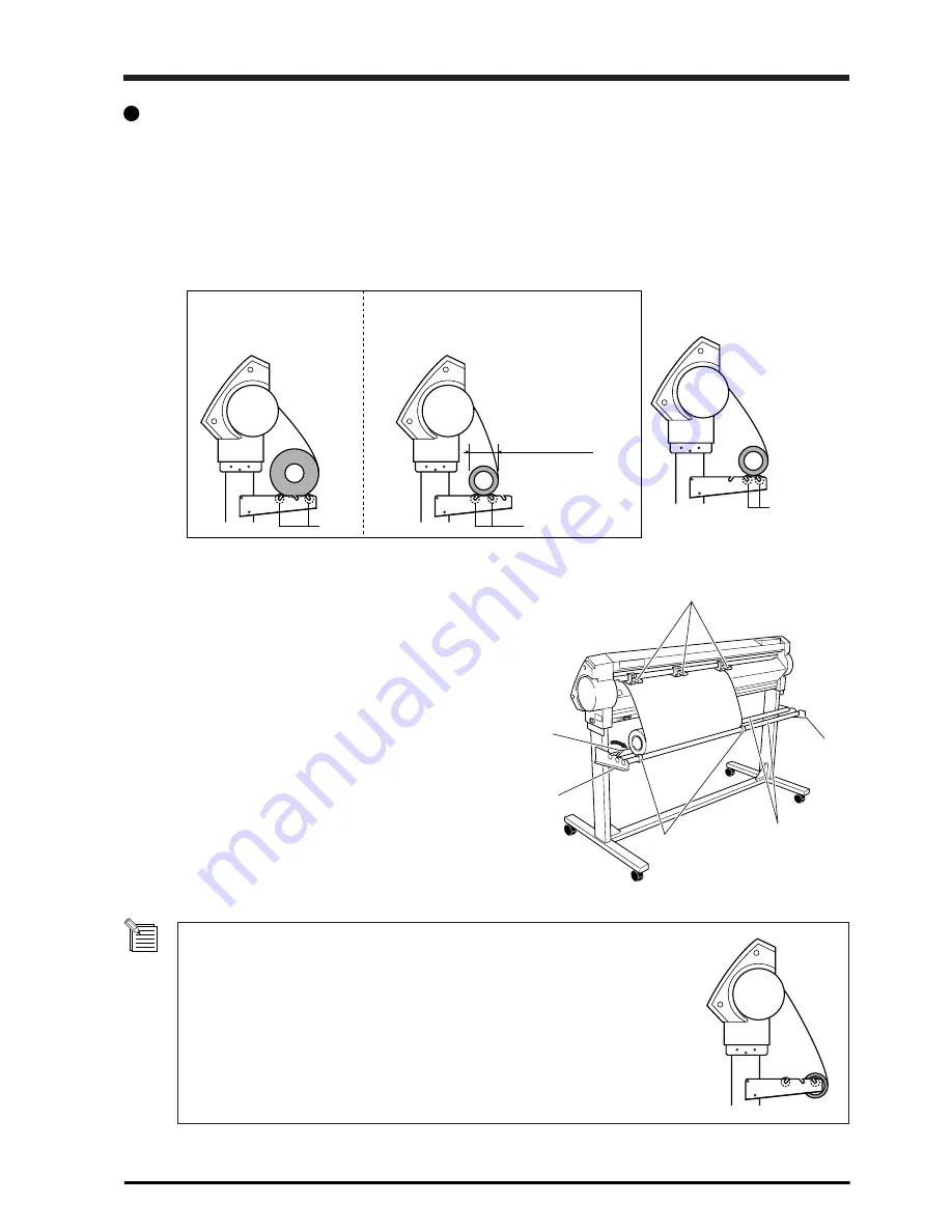
Shafts

Shafts

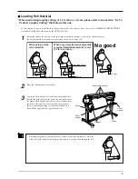
less than 72 mm

Shafts

When using a thick 
roll of material

When only a small amount of material 
remains (material diameter is 72 mm 
(2-7/8 in.) or less)...

No good

Sheet Loading Lever

Sheet 
hanger

Sheet 
hanger

Brake

Shafts

Stopper

 Loading Roll Material

* When performing lengthy cutting of 1.5 m (60 in.) or more, please refer to the section “5-3 To

Perform Lengthy Cutting” that follows this one.

For information on how to install the sheet hanger, shaft, brake, and stoppers, please refer to the “ASSEMBLY INSTRUCTIONS”
for the PNS-502/402/302 (the stand for the CX-500/400/300).

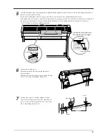
1

Mount the shaft at the location on the sheet hanger shown in the figure to match the outer diameter of
the rolled material. If mounted at an incorrect position, the roll may fall.

2

Place the rolled material on the shaft.

3

Lower the sheet loading levers and raise the pinch rollers.
Release the brake and pass the end of the material between
the pinch rollers and the grit rollers so that it extends from
the front of the unit. You can easily load the material so
that it is straight by pulling out the material until it is in
line with the upper and lower guideline marks.

Performing high-speed cutting when only a little roll material remains may cause the
roll to fall off the shaft. If this happens, it may help to pass the shaft through the roll.

Summary of Contents for CX-300

Page 1: ...nd the specifications of this product are subject to change without notice The operation manual and the product have been prepared and tested as much as possible If you find any misprint or error please inform us Roland DG Corp assumes no responsibility for any direct or indirect loss or damage which may occur through use of this product regardless of any failure to perform on the part of this pro...

Page 2: ...4 Loading Flat Material Standard size Material Cut Material Etc 30 5 5 Repeating the Same Cutting 31 5 6 Front Loading 32 5 7 The Overcut Feature 35 5 8 The Preset Feature 36 5 9 The Crop Mark Feature 38 6 About the Blades and Materials 40 6 1 Blade and Material Combinations 40 6 2 About Special Materials 41 7 Descriptions of Features 42 7 1 Key Operations 42 7 2 Display Menus Flowchart 43 7 3 Lis...

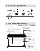
Page 3: ...arating knife This cuts off a piece of material from rolled material Power Switch ON when switched to OFF when switched to Guide line These are used as guides for making sure the loaded material is straight Align the right hand edge of the material with these scale lines Grit Roller The pinch rollers and grit rollers grip the material and move it forward and back ward Movable Pinch Roller Right Se...

Page 4: ...ers the menu mode See 7 1 PEN FORCE Slider This slider performs fine adjustment of the blade force See 4 3 SHEET CUT Key This severs the material ENTER Key This confirms menu items and stores settings in memory TEST CUT Key This performs a cutting test You can use this to make sure the blade force blade compensation and cutting speed are appropriate See 4 3 CURSOR Keys Sheet Loading Lever These ra...

Page 5: ... during operation Places with excessive vibration Release the caster locks for the stand before attempting to move Otherwise the unit may tip over and cause injury Install in a level and stable location Otherwise the unit may tip over and cause injury For an explanation of how to assemble the unit and the stand PNS 502 402 302 refer to the ASSEMBLY INSTRUCTIONS included with the stand When using t...

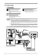
Page 6: ...lded USB cable Do not interpose a hub in the USB cable It is possible to use the CX 500 400 300 with it connected by both cables at the same time Data is received with the port to which data is sent first taking priority When cutting using the data received first is completed data from the other port is received Securely connect the power cord computer I O cable and so on so that they will not be ...

Page 7: ...the front right surface of the unit to turn on the power 3 4 Installing and Setting Up the Driver The included Roland Software Package CD ROM contains softwares such as a driver Refer to the included Startup Manual and install it on your computer ...

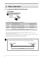
Page 8: ...r more You can also use flat material such as standard size and piece material For more information see 5 4 Loading Flat Material Standard size Material Piece Material Etc The grit rollers pinch rollers that secure the material vary from one model to another and settable ranges are determined for the left and right movable pinch rollers See Material Loading Position on the following page Setting a...

Page 9: ...CX 500 400 300 1 Mount the shaft at the location on the sheet hanger shown in the figure to match the outer diameter of the rolled material If mounted at an incorrect position the roll may fall 2 Place the rolled material on the shaft 3 Lower the sheet loading levers and raise the pinch rollers Release the brake and pass the end of the material between the pinch rollers and the grit rollers so tha...

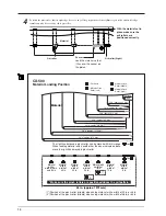
Page 10: ...r can be moved within this range When loading material with a width other than one indicated above move the right hand movable pinch roller 1 Position of the pinch roller middle when using material with a width of 30 in or 36 in 2 Position of the pinch roller middle when using material with a width of 48 in or 54 in Grit Roller Movable Pinch Roller Left Movable Pinch Roller Right Movable Pinch Rol...

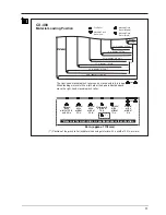
Page 11: ...able Pinch Roller Left Movable Pinch Roller Right Movable Pinch Roller Middle The right hand movable pinch roller can be moved within this range When loading material with a width other than one indicated above move the right hand movable pinch roller Material with a width of 36 in and 46 in Material with a width of 30 in Material with a width of 24 in Material with a width of 12 in Material with ...

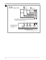
Page 12: ...h a width of 12 in Grit Roller Movable Pinch Roller Left Movable Pinch Roller Right Material with a width of 18 in Material with a width of 24 in and 30 in and 36 in 36 in approx 915 mm Material CX 300 Material Loading Position The right hand movable pinch roller can be moved within this range When loading material with a width other than one indicated above move the right hand movable pinch rolle...

Page 13: ...ng lever at the back of the unit Load the material so that it is straight If the material is crooked straight material feed cannot be performed The CX 300 does not have a middle pinch roller Screws Brake Roll material 6 Lift the sheet loading lever The pinch rollers are lowered and the material is secured in place When using a material which is narrower than 762 mm 30 in do not lower the middle pi...

Page 14: ...t rollers Reposition the material to match this new alignment then lift the sheet loading levers to hold the material in place When using roll material before you perform cutting you need to pull out the required length of material from the roll For more information refer to Material Test Feed in 4 5 Starting Cutting 4 2 Installing a Blade Do not touch the tip of the blade with your fingers Doing ...

Page 15: ...carrying out actual cutting you may wish to perform a cutting test to check whether the unit produces the cutout satisfacto rily The cutting test should be repeated until the appropriate cutting conditions for the material in use are discovered Cutting Test 1 Use the and keys to move the tool carriage to the place where the cutting test is to be performed Note that an area of approximately 2 squar...

Page 16: ...n the material is being cut Take care not to set the blade force excessively high Adjusting the Blade Force Examine the result of the cutting test and adjust the blade force accordingly Setting range 20 to 350 gf in increments of 10 gf After using the control panel to set the blade force if you want to raise or lower the blade force slightly you can use the PEN FORCE slider to make fine adjustment...

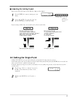
Page 17: ... the display Setting range 1 to 85 cm s settable in increments of 1 cm s Cutting speed adjustment 2 Use the and keys to adjust the value then press the ENTER key to enable the setting Incorrect cutting conditions may cause symptoms such as those described below 4 4 Setting the Origin Point With the CX 500 400 300 you can set the location where cutting starts the origin point at any position If the...

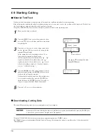
Page 18: ... material feed toward the front and signifies material feed toward the back is used when front loading is employed For more informa tion see 5 6 Front Loading 4 Press the ENTER key The screen changes to the one shown at right Pressing the ENTER key once more feeds out the set length of material If the material is crooked and looks like it might come loose from the pinch rollers press the PAUSE key...

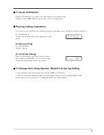
Page 19: ...low of data being sent by the computer Then hold down the ENTER key for 0 5 seconds or longer Cutting stops and the display returns to the top menu To Change the Cutting Speed or Blade Force During Cutting You can change the settings during cutting by pressing the SPEED or FORCE key You can also perform fine adjustment in blade force while cutting is in progress by using the PEN FORCE slider For i...

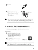
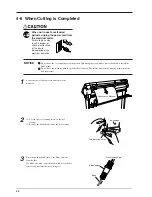
Page 20: ...ool securing screw tightened Tightening the screw makes it more difficult to install the blade holder Do not leave the machine with the pinch rollers lowered The rollers may deform making normal material feed impossible NOTICE 1 Lower the sheet loading levers and remove the material 2 1 Loosen the tool securing screw on the tool carriage 2 Remove the blade holder from the tool carriage 3 Press the...

Page 21: ...21 POWER ERROR LED goes out 4 Turn off the power ...

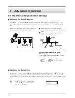
Page 22: ...t of blade extension which is approximately equal to the cutting in amount Setting the blade force slightly higher than normal achieves a stable cutting in amount Rough Estimate for the Amount of Blade Extension Use the following dimension as a rough estimate for setting the amount of blade extension Amount of blade extension Thickness of the material portion 2 Thickness of the carrier paper Adjus...

Page 23: ...e is too small the corners will appear slightly rounded as illustrated by B an offset value which is too large will result in a cut figure similar to C When you are adjusting the blade offset we recommend first adjusting the blade force and the amount of blade extension Changing the Speed When Raised Up Speed With the CX 500 400 300 you can set the speed for movement to the next cutting location w...

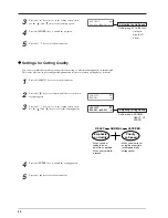
Page 24: ...4 Press the ENTER key to enable the up speed 5 Press the key to exit the menu mode Settings for Cutting Quality You can select whether speed is given priority in cutting or whether cutting quality is emphasized This is also effective in preventing misalignment and motor errors when cutting heavy material 1 Press the MENU key to enter the menu mode 2 Press the key several times until the screen sho...

Page 25: ...cording to the selection made for SELECT SHEET with the operation panel when loading material ROLL Set near the left hand pinch roller PIECE Material size is detected and the origin is set at the lower left area of the material F EDGE Set at the front left edge of the material R EDGE Set at the inner left edge of the material When using the Front loading For more information see the following page...

Page 26: ...nt is set near the left pinch roller When the length of the material is 1 600 mm 63 in or longer the material is determined to be roll material The origin point is set in the same way as for ROLL above 0 0 25 mm 1 in Material Pinch Roller Margin F EDGE When performing cutting from as close as possible to the front edge of the material Set the origin point at a location having a margin of 25 mm fro...

Page 27: ...raphics by 90 degrees Note that the coordinate axes change when rotated Make the settings to match the program you re using When you are perform ing output using the CAMM 1 driver set this to 0deg When rotated 90 degrees the X axis Y axis and origin point change as follows 1 Press the MENU key to enter the menu mode then press the key several times until the screen shown at right appears 2 Press t...

Page 28: ...oint is the margin See The Location of the Origin Point Immediately After Loading Material elsewhere in this section When you have separated the material using the SHEET CUT key this is the value set for MARGIN at the AUTOCUT MENU Refer to 7 3 List of Functions When performing material feed or cutting be sure to release the brake Attempting to perform material feed or cutting with the brake engage...

Page 29: ...gure Position the middle pinch roller over the grit roller that lies between the left and right hand pinch rollers 4 While keeping the material stretched taut raise the sheet loading lever to secure the material in place When using a material which is narrower than 762 mm 30 in do not lower the middle pinch roller 5 Position the stoppers so that they lightly touch the edges of the roll and secure ...

Page 30: ...m 1 0m AREA MOVE START AREA MOVE 1 0m 5 0m W 500mm L____mm 5 4 Loading Flat Material Standard size Material Cut Material Etc In addition to roll material you can also load flat material such as piece material on this machine If the material strikes the shaft during cutting remove the shaft 1 Lower the sheet loading levers and pass the material between the pinch rollers and the grit rollers 2 Follo...

Page 31: ...ome loose from the pinch rollers or actually does come loose please reload the material 5 5 Repeating the Same Cutting The Replot feature allows you to create numerous copies of same cutting 1 Press the MENU key to enter the menu mode use the key to select REPLOT then press the key to display the replot execution screen 2 Pressing the ENTER key starts replotting The Replot function calls up all da...

Page 32: ...Loading Material 1 Refer to 4 1 Loading the Material Roll Material and load the material 2 At SELECT SHEET select either ROLL or R EDGE Do not select F EDGE 3 Follow the steps in Setting the Origin Point in the next section to set a new origin point In particular not that if you have selected R EDGE cutting cannot be performed unless you set a new origin point You cannot perform a cutting test imm...

Page 33: ...uired cutting area available ROLL Set near the left hand pinch roller R EDGE Set at the inner left edge of the material 1 Make sure the brake is released 2 Press the MENU key to enter the menu mode 3 Press the key several times until the screen shown at right appears 4 Press the key to move to the setting screen then use the and keys to set the required material length for cutting Set a value that...

Page 34: ...from the computer the material is fed toward the back without any cutting or printing performed A new origin point is set and the cutting area is made available automatically Cutting then starts When cutting finishes the tool returns to the origin point When you send the next set of cutting data leave the location of the tool unchanged 1 2 3 4 The tool position when cutting starts is used as the p...

Page 35: ... CUT ENABLE Cutting line Cutting line 5 7 The Overcut Feature This cuts an excess margin of 1 mm 0 04 in from the first and last line segments This is effective when you want to finish with angles that are especially sharp such as when cutting thick material This should normally be left set at DISABLE When you want to cut especially attractive corners set it to ENABLE Note that when you are cuttin...

Page 36: ...e menu mode 1 Use the display menu to make the settings for cutting conditions matched to the tool and material in use You can set the following five types of parameters Blade force FORCE key Offset Menu mode OFFSET Cutting speed SPEED key Cutting quality Menu mode QUALITY Up speed Menu mode UPSPEED Storing is now completed When you store to a preset number any cutting conditions already stored to...

Page 37: ...cted is called up and the display changes as shown at right Deleting Settings You can delete the stored settings for cutting conditions returning them to their factory defaults Please note that all preset numbers from 1 to 8 are deleted 1 Press the MENU key to enter the menu mode 2 3 Press the key to move to the FACTORY DEFAULT menu 4 Press the key to move to the setting screen then use the and ke...

Page 38: ...lel to the material Figure B The methods for setting crop marks are described bellow Please refer to the figures shown above while making this setting Material Material When the crop mark setting has not been made Crop mark Cutting line B When the crop mark settings has been made A Accurate cutting around the graphic becomes possible Align point Base point Accurate cutting around the graphic is no...

Page 39: ...rriage to the crop mark printed at the lower right of the material Line up the alignment tool with the center of the crop mark After the alignment tool has been positioned correctly press the ENTER key 7 When the settings are successful use the key to quit the menu mode 6 When the crop mark setting has been made success fully the display shows screen A then returns to the screen shown in step 2 Re...

Page 40: ... to serve as a general guide when cutting materials of identical type When you are cutting small text character height of 3 mm for alphanumeric characters or more ZEC U3017 can produce more attractive cutting results than other blades Use the included blade under conditions equivalent to those for the ZEC U5025 Material General Signage Vinyl Polyolefin material General Signage Vinyl Fluorescent Vi...

Page 41: ...ith a material thickness of 1 mm 0 04 in or less B Materials with only carrier paper on both flanks of the material Position the left and right pinch rollers above the strips of carrier paper C Materials with carrier paper which is hard enough to withstand material feed A 1 mm 0 04 in or less Carrier paper Material B 15 mm 5 8 in or more B 15 mm 5 8 in or more Material with sprocket feed holes Mat...

Page 42: ...enu Mode Pressing MENU enters the menu mode Key operations in the menu mode are as follows Moving to the previous menu screen or the next menu screen Selecting a setting value Moving the material Moving to the setting screen Moving the carriage Moving to the previous screen quitting the menu mode Moving the carriage ENTER Executing a menu item Enabling a setting Pressing the key without pressing E...

Page 43: ...ting data FORCE Blade force adjustment SHEET CUT 0 5 seconds This cuts off the material This is also available at the cutting area display screen SPEED Cutting speed adjustment Use the cursor keys to move the carriage Press ORIGIN for 0 5 seconds to set the new origin point PAUSE This resumes cutting without change ENTER 0 5 seconds This quits cutting TEST CUT 0 5 seconds This performs a cutting t...

Page 44: ...ettings of the top screen to the selected preset number 0deg 90deg TYPE1 TYPE2 DISABLE ENABLE 40 to 85 cm s 1 cm s step AREA MOVE 1 0m AREA MOVE 1 0m 1 0m AREA MOVE START NOW AREA MOVING OFFSET 0 250mm OFFSET 0 250mm 0 250mm UPSPEED 50cm s UPSPEED 50cm s 50cm s QUALITY NORMAL QUALITY NORMAL NORMAL SETUP SETUP UNSETUP AXIS ROTATE 0deg AXIS ROTATE 0deg 0deg PRESET PRESET1 PRESET1 SUB MENU AUTOCUT ME...

Page 45: ...MENU OVER CUT DISABLE DISABLE AUTO PREFEED DISABLE AUTO PREFEED DISABLE DISABLE SMOOTHING ENABLE SMOOTHING ENABLE ENABLE CALIB X 0 00 CALIB X 0 00 0 00 CALIB Y 0 00 CALIB Y 0 00 0 00 CROPMARK COMMAND MENU MARGIN 30mm MARGIN 30mm 30mm AUTOCUT PASSES 1 AUTOCUT PASSES 1 1 COMMAND MODE AUTO COMMAND MODE AUTO AUTO BASE POINT 0mm 0mm ALIGNPOINT 0mm 0mm CROPMARK SETTING COMPLETED CROPMARK SETTING FAILED ...

Page 46: ...n and the key to move to the previous screen ENTER This enables runs or stores the item shown on the display ORIGIN Holding down this key for 0 5 seconds or longer sets the origin point at the present blade position the blade center SHEET CUT Holding down this key for 0 5 seconds or longer cuts off the material at the present position of the separating knife Press this to sever an already cut piec...

Page 47: ...the cutting coordinate origin by 90 degrees 0deg 90deg 0deg The default setting is 0deg which means that the origin is at the bottom left of the material Setting this to 90deg moves the origin to the bottom right of the material thereby rotating the cutting pattern by 90 degrees Don t forget that the coordinate axis changes when the origin is rotated AREA MOVE This moves the material by the length...

Page 48: ...ep cutting off the material AUTOCUT This sets the number of times material cutoff is 1 2 1 PASSES performed once for 1 or twice for 2 When working with thicker material or other material that s difficult to cut set this to 2 Pressing the SHEET CUT key once performs material cutoff the number of times set here COMMAND COMMAND This selection enables the type of instructions that are AUTO AUTO MENU M...

Page 49: ...tting DISABLE ENABLE DISABLE PREFEED If this is set to ENABLE when cutting data is sent from the computer the plotter will automatically execute cutting after a 1 m 39 3 8 in feed toward the front Some data may cause feed over 1 m 39 3 8 in such as when the next point of movement is located more than 1 m 39 3 8 in to the rear If the AREA MOVE function is used to feed the material in advance the ma...

Page 50: ...wered and the pinch rollers raised use a commercially available brush to remove dust and other detritus Brush horizontally while rotating the grit rollers If dust builds up it may prevent the material from being held securely and degrade plot precision Cleaning the pinch rollers Lower the sheet loading levers and raise the pinch rollers Use a cloth moistened with water then wrung well and wipe gen...

Page 51: ... impossible Replace with a new blade holder When the blade holder has been in use for a prolonged period the bearing that supports the blade deteriorates impeding rotation of the blade Continued use while in this state may make attractive cutting impossible because the blade tip cannot rotate easily If corners and curves are not cut attractively or if cutting is discontinuous refer to 8 1 Cleaning...

Page 52: ... to replace the knife 3 Replace with a new knife 2 Remove the separating knife 1 Loosen the screw until it slips out 2 Grasp the screw portion and slowly pull it out in the direction of the arrow Do not pull back while doing this 4 Install the separating knife 1 Grasp the screw portion and slowly insert it into the groove Take care to ensure that the knife does not slip 2 Tighten the screw Positio...

Page 53: ...Refer to 4 1 Loading the Material Roll Material and load material 3 4 Press the key several times until the screen shown at right appears 5 Press the key to move to the submenu 6 Use the and keys to select DEMO CUT Press the MENU key to enter the menu mode 7 Press the ENTER key The operation check starts Operation is correct if the cutting shown in the figure is performed 2 Refer to 4 2 Installing...

Page 54: ...le specified in your software Is the machine in the setup state If the SETUP LED is not lit cutting cannot be performed even when data is sent Are the settings for the software driver correct Make the correct settings for the output port Are the computer and the CX 500 400 300 connected correctly Correctly connect the computer and the CX 500 400 300 see 3 2 Connections Is the OS set up correctly C...

Page 55: ...across a long distance without initial material feed or when the material is abruptly pulled from the roll during cutting In this case turn the power off and back on again if a media jam has occurred clear the jam before turning the power back on For large cutting data with a roll material use the AREA MOVE function on the display menu to feed the roll material by the length of the cut ensure a sm...

Page 56: ...out a cutting test and set the appropriate values Refer to 5 1 Detailed Cutting condition Settings and 4 3 Adjusting the Blade Force and Cutting Speed Are the amount of blade extension and blade force appropriate for the material being cut Adjust the amount of blade extension and the blade force appropriately Refer to 5 1 Detailed Cutting condition Settings and 4 3 Adjusting the Blade Force and Cu...

Page 57: ... CX 500 400 300 during cutting Such contact may not only damage the material but could also make normal material advancing impossible and cause the material to slip Is the material being cut loaded straight If the front edge of the material you are working with is at an angle cut off the odd shaped part to make it straight then align it so that it is parallel with the grit roller If the material i...

Page 58: ...elow In almost all cases the cause is receiving incorrect data For information about corrective action go to 9 2 What to Do If and refer to CX 500 400 300 Troubleshooting Error massage Meaning Appears if an instruction that the CX 500 400 300 cannot interpret is sent Additionally this error is generated if an instruction from the mode2 set is sent when the unit has been set to recognize mode1 or v...

Page 59: ...lay unit 20 character by 2 lines Maximum 0 8A 100V to 240V 10 50 60 Hz Cutting mode under 62dB A Standby mode under 40dB A According to ISO 7779 Width 737 mm 29 in Length 24998 mm 984 1 8 in Min 50 mm 2 in Max 915 mm 36 in 50 to 540 mm 2 in to 21 in 582 to 915 mm 23 in to 36 in 0 to 812 mm 0 in to 32 in CX 300 Main unit With stand Main unit With stand For items indicates by an asterisk please see ...

Page 60: ...length plus 0 2 m and set the material correctly Cutting of the following data one time X Y Origin 1 The letters are cut in order starting with R 2 After the last letter P has been cut the machine returns to the origin point and the outer border is cut The origin is rotated 90 degrees AXIS ROTATE on the display menu is set to 90deg Feed length Material with a width exceeding 610 mm 24 in 4 000 mm ...

Page 61: ...1 1 Transmission speed 12Mbps Full Speed Device Data format NRZI Compatible connector Series B Rated cable length 3 m USB Parallel connector in compliance with specifications of Centronics 1 19 18 36 3 3K 100 5 V 5 V Signal number Terminal number Signal number Pin Connection NC 36 18 HIGH HIGH 35 17 GND NC 34 16 GND GND 33 15 NC HIGH 32 14 NC NC 31 13 HIGH 30 12 GND 29 11 BUSY 28 10 ACK 27 9 D7 26...

Page 62: ...S Q N C E A G K T mode 2 Instruction Compatibility Instruction Compatibility Instruction Compatibility Instruction Compatibility Instruction Compatibility AA AR CA CI CP CS DF DI DR DT EA ER EW FT IM IN IP IW LB LT OA OC OE OF OH OI OO OP OS OW PA PD PR PT PU RA RR SA SC SI SL SM SR SS SP TL UC VS WD WG XT YT Instruction in mode 1 and mode 2 Instruction Compatibility Instruction Compatibility Inst...

Page 63: ...63 MEMO ...

Page 64: ...R5 020403 ...

Reviews:

Related manuals for CX-300