Placement
• Do not expose the product to direct sunlight,
place it near devices that radiate heat, leave it
inside an enclosed vehicle, or otherwise subject
it to temperature extremes. Excessive heat can
deform or discolor the product.
• Do not allow rubber, vinyl, or similar materials
to remain on this product for long periods of
time. Such objects can discolor or otherwise
harmfully aff ect the fi nish.
• Depending on the material and temperature of
the surface on which you place the product, its
rubber feet may discolor or mar the surface.
As a precautionary measure, we recommend
the use of a drum mat.
• Do not put anything that contains water on
this product. Also, avoid the use of insecticides,
perfumes, alcohol, nail polish, spray cans, etc.,
near the product. Swiftly wipe away any liquid
that spills on the product using a dry, soft cloth.
Maintenance
• For everyday cleaning wipe the product with
a soft, dry cloth or one that has been slightly
dampened with water. To remove stubborn
dirt, use a cloth impregnated with a mild, non-
abrasive detergent. Afterwards, be sure to wipe
the product thoroughly with a soft, dry cloth.
• Never use benzine, thinners, alcohol or
solvents of any kind, to avoid the possibility of
discoloration and/or deformation.
WARNING
Do not disassemble or modify by yourself
Do not open or perform any internal
modifi cations on the product. (The
only exception would be where this
manual provides specifi c instructions
which should be followed in order to put in place
user-installable options.)
Do not repair or replace parts by yourself
Do not attempt to repair the product,
or replace parts within it (except
when this manual provides specifi c
instructions directing you to do so).
Refer all servicing to your retailer, the nearest
Roland Service Center, or an authorized Roland
distributor, as listed on the “Information.”
Do not use or store in the following types of locations
• Subject to temperature extremes
(e.g., direct sunlight in an enclosed
vehicle, near a heating duct, on top of
heat-generating equipment); or are
• Damp (e.g., baths, washrooms, on
wet fl oors); or are
• Exposed to steam or smoke; or are
• Subject to salt exposure; or are
• Humid; or are
• Exposed to rain; or are
• Dusty or sandy; or are
• Subject to high levels of vibration and
shakiness.
Do not place in an unstable location
Make sure you always have the product
placed so it is level and sure to remain
stable. Never place it on stands that
could wobble, or on inclined surfaces.
WARNING
Adults must provide supervision in places where
children are present
When using the product in locations
where children are present, be careful
so no mishandling of the product can
take place. An adult should always be
on hand to provide supervision and guidance.
Do not drop or subject to strong impact
Protect the product from strong
impact.
(Do not drop it!)
CAUTION
Avoid climbing on top of the product, or placing heavy
objects on it
Never climb on top of, nor place heavy
objects on the product.
Take care not to get fi ngers pinched by moving parts
Take care not to pinch your fi ngers
or other parts of your body when
operating the moving parts of the
pedal or drum throne. If small children
use this equipment, make sure they have adult
supervision and guidance.
Keep small items out of the reach of children
Keep removable parts (screws, nuts,
memory lock) out of the reach of small
children to prevent them from being
swallowed accidentally.
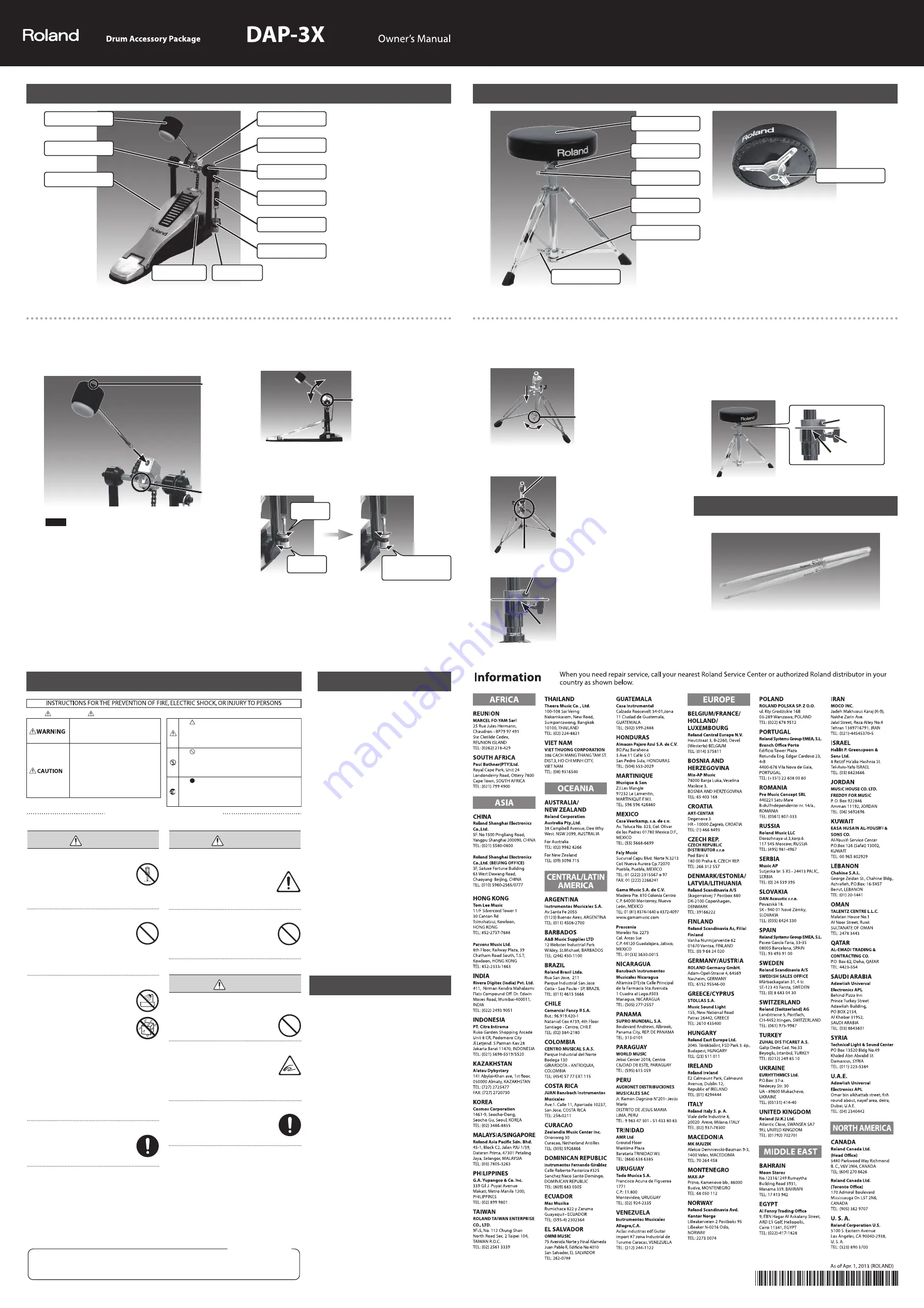
1.
Open the tripod
Loosen wing bolt “B” and open the tripod all the way to the stopper.
When the tripod is fully open, fi rmly fasten wing bolt “B,” which you
loosened earlier.
Wing bolt “B”
2.
Attach the seat
Loosen wing bolt “A,” raise the upper
pipe to the desired height, and
provisionally tighten wing bolt “A,” so
that the upper pipe does not drop.
Next, use the drum key to loosen
the square-head bolt of the memory
lock, and lower the memory lock to
the position shown in the illustration
below.
Attach the seat, and tighten the T-bolt
to fasten it securely.
3.
Adjust the height of the seat
Loosen wing bolt “A” and adjust the throne to the desired height.
When you’ve adjusted the height as desired, securely tighten wing bolt
“A.” Next, align the memory lock to the position shown in the illustration
below, and securely tighten the square-head bolt of the memory lock
to fasten it.
* Using the memory lock will prevent the seat from descending
during performance.
Square-head
bolt of the
memory lock
Wing bolt
“A”
Drumsticks
Use the drumsticks to play the V-Drums.
Upper pipe
Wing bolt “A”
Square-head bolt of
the memory lock
Kick Pedal
Beater
Square-Head bolt “A”
Foot board
Beater holder
Square-Head bolt “B”
Angle adjuster
Roller
Spring
Lock nut
Adjusting nut
Hoop clamp
Assembling the Kick Pedal
Before using this product, carefully read the sections entitled: “USING THE UNIT SAFELY” and “IMPORTANT NOTES”.
These sections provide important information concerning the proper operation of the product. Additionally, in order to feel assured that you have gained a good grasp of
every feature provided by your new product, Owner’s manual should be read in its entirety. The manual should be saved and kept on hand as a convenient reference.
1.
Attach the beater
Use the drum key to loosen square-head bolt “A.” Next, insert the beater
into the beater holder with the prastic beater facing the head, as shown
in the illustration below. Then, secure it by tightening square-head bolt
“A,” which you loosened earlier.
Square-Head
bolt “A”
Plastic beater
NOTE
The mesh head can wear down a felt beater. We recommend using a
plastic beater.
2.
Attach to the V-Drums kick pad
Insert the kick pad’s pedal attachment plate into the hoop clamp of the
kick pedal, and fasten it.
* For details, refer to the owner’s manual of the V-Drums kick pad.
3.
Adjust the angle of the beater
Loosen square-head bolt “B” and adjust the beater to the desired angle.
When you’ve set the angle, fi rmly tighten square-head bolt “B” to secure
it.
Square-Head
bolt “B”
4.
Adjust the spring
Loosen the adjusting nut to adjust the tension of the spring.
Once you’ve got the tension adjusted to your liking, fi rmly secure the lock
nut against the adjusting nut.
Loosen
Adjust
Secure the lock nut
against the adjusting nut
* Take care not to pinch your
fi ngers during assembly.
* There is a risk of injury if the kick
pedal is used barefoot. Please
wear suitable footwear.
Drum Throne
Seat
Memory lock
Wing bolt “A”
Tripod
Stopper
Wing bolt “B”
T-bolt
Assembling the Drum Throne
Main Specifi cations
Roland DAP-3X: Drum Accessory Package
<Kick Pedal>
Weight
2.2 kg (4 lbs 14 oz)
Beater
Plastic/felt
<Drum Throne>
Seat
Diameter: 305 mm (12-1/16 inches)
Height
490–670 mm (19-5/16–26-7/16 inches)
Weight
4.3 kg (9 lbs 8 oz)
<Drumsticks>
Length
406 mm (16 inches)
Material
Ash
* In the interest of product improvement, the
specifi cations and/or appearance of this
product are subject to change without prior
notice.
Copyright © 2012 ROLAND CORPORATION
All rights reserved. No part of this publication may be reproduced in any form without the written permission of ROLAND CORPORATION.
Roland and V-Drums are either registered trademarks or trademarks of Roland Corporation in the United States and/or other countries.
* Take care not to pinch your fi ngers
during assembly.
* Use the memory lock correctly, so
the seat doesn’t descend while you’re
performing.
* Never tilt the throne while seated on
it, and try to avoid unnatural postures
while using the throne; doing so may
cause malfunction or deformation.
IMPORTANT NOTES
WARNING
This product contains chemicals known to cause cancer, birth defects and other reproductive harm, including lead.
For C.A. US (Proposition 65)
Used for instructions intended to alert the
user to the risk of injury or material
damage should the unit be used
improperly.
* Material damage refers to damage or
other adverse effects caused with
respect to the home and all its
furnishings, as well to domestic animals
or pets.
Used for instructions intended to alert the
user to the risk of death or severe injury
should the unit be used improperly.
The symbol alerts the user to things that must be
carried out. The specific thing that must be done is
indicated by the design contained within the circle. In the
case of the symbol at left, it means that the power-cord
plug must be unplugged from the outlet.
The symbol alerts the user to important instructions or
warnings.The specific meaning of the symbol is
determined by the design contained within the triangle. In
the case of the symbol at left, it is used for general
cautions, warnings, or alerts to danger.
The symbol alerts the user to items that must never be
carried out (are forbidden). The specific thing that must
not be done is indicated by the design contained within
the circle. In the case of the symbol at left, it means that
the unit must never be disassembled.
About WARNING and CAUTION Notices
About the Symbols
ALWAYS OBSERVE THE FOLLOWING
USING THE UNIT SAFELY
*
5
1
0
0
0
2
5
6
5
3
-
0
3
*


