15
Mar.2001
SP-303
1.
Check the function of the CPU (IC23) and FLASH MEMORY 4M, 8M
(IC22, IC24).
2.
Check the function of the CPU RAM (IC23) and DRAM (IC27).
3.
Check the function of the DSP (IC9) and CPU (IC23).
4.
Check the function of the DSP (IC9) and SRAM (IC13).
*
When entering the test mode in [1. Entering the test mode] 3., the test is
completed automatically and returns to the selection screen of each test.
2. SMARTMEDIA & SUM CHECK
Check the writing of the factory-shipped sample and pattern data and
Checksum.
*
In this test, pressing the [CANCEL] button retests only the [2.2 SUM CHECK].
2.1 SMARTMEDIA CHECK
Write the factory-shipped sample and pattern data into the machine in use
from the SmartMedia that contains the factory preset data.
During writing, “uPd” appears and the dot blinks.
After writing is completed, the test proceeds to the next test automatically.
*
To perform this process, a SmartMedia containing the factory data is required.
SmartMedia containing the factory data can be created using a new machine
and new SmartMedia.
(See [SAVING USER DATA & RELOADING SAVED DATA] for the method)
Also, SmartMedia containing factory data (P/No.17041008) can be supplied as
a service part from the service center.
*
While writing to the machine in use, the [CANCEL] and [REC] buttons cannot
be operated.
*
If the SmartMedia is not inserted, writing is not performed and the machine
automatically proceeds to the next test.
2.2 SUM CHECK
Checksum is displayed.
2.2 Upon reaching Checksum without any problems, proceed to the next test
by pressing the [REC] button.
3.SWITCH & LED CHECK
Check the SWITCH function and display appearance.
Each segment and point of the display lights up sequentially. Check that
everything lights up.
Check the function by pressing each SW. The peak LED lights up when the
SWITCH is pressed.
LEDs can be turned off by pressing the appropriate SWITCH.
*
When two SWITCHes are pressed simultaneously, “Err” is displayed and the
test mode stops.
In which case, turn the power off and on again and start the test from the
beginning.
After pressing all the SWITCHes, “End” appears.
Pressing the blinking [REC] button proceeds to the next test.
*
When entering the test mode in [1. Entering the test mode] 1., the machine
automatically proceeds to the next test after the present test is completed.
4. VOLUME CHECK
“CtL” appears. Check the function of each handle.
Rotate the CTRL1 handle “all the way to the left.”
Rotate the CTRL1 handle “all the way to the right.”
At this time, check to see that the display changes from “0-127.”
Repeat the same procedure for CTRL2 and CTRL3/MFX and check that the
same display changes occur. When all handles function without any problem,
“End” appears. Pressing the blinking [REC] button proceeds to the next test.
*
When entering the test mode in [1. Entering the test mode] 1., the machine
automatically proceeds to the next test after the present test is completed.
*
When operating handles other than the ones you are checking, “Err” appears
and the test stops.
Press the [CANCEL] button and execute [4. VOLUME CHECK] again from the
beginning.
5. LINE IN/OUT CHECK
“Lin” appears.
Check the function of the signal input to INPUT L and R at the time of output
from OUTPUT L and R .
5.1 INPUT/OUTPUT LEVEL CHECK
Set the oscillator to a rectangular “200 Hz and 100m Vp-p” wave and input to
INPUT L.
Rotate the VOLUME handle “all the way to the right.”
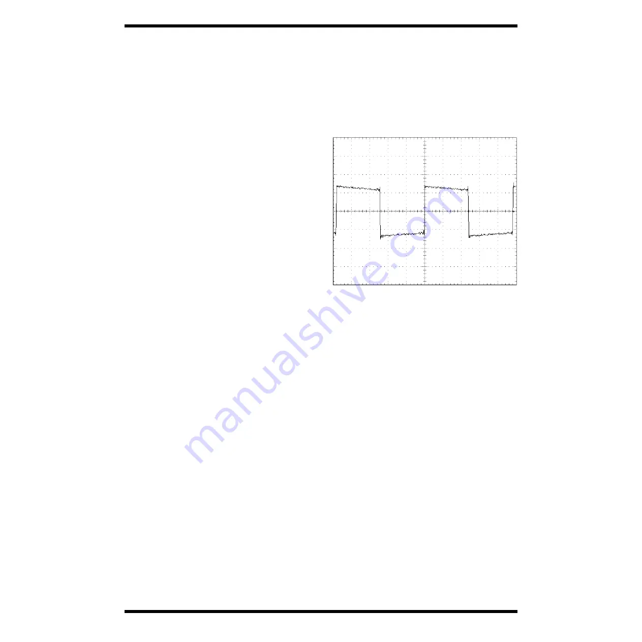
Connect OUTPUT L to the oscilloscope and check that the following
rectangular wave is output.
fig.fig1
(200 mV/DIV, 1.00 ms/DIV)
Rotate the VOLUME handle “all the way to the right”-> ”all the way to the
left” -> “all the way to the right” and check that the amplitude of the
waveform changes from maximum -> minimum (without amplitude) ->
maximum.
In the same way, check that the above waveform is output by connecting the
oscillator and oscilloscope to INPUT R and OUTPUT R, and that the amplitude
changes when the VOLUME handle is operated.
5.2 Residual noise check
Rotate the MIC VOLUME handle “all the way to the left” and VOLUME
handle “all the way to the right,” and connect the Noisemeter to OUTPUT L.
Set the Noisemeter to “JIS-A(IHF-A)” and check that the following value is
acquired for residual noise.
OUTPUT L -70.0[dBm] or below
OUTPUT L -70.0[dBm] or below
In the same way, check to see if the above value is acquired for residual noise
for OUTPUT R.
Pressing the blinking [REC] button proceeds to the next test.
6. PHONE CHECK
“PHo” appears on the display.
Check the function of the signal input to INPUT L and R at the time of output
from the PHONE terminal.
6.1 INPUT/PHONE OUT LEVEL CHECK
Set the oscillator to rectangular “200 Hz and 100m Vp-p” wave and input to
INPUT L.
Rotate the VOLUME handle “all the way to the right.”
Connect the L channel side of the PHONE terminal to the oscilloscope and
check that the following rectangular wave is output.
Summary of Contents for Dr. Sample SP-303
Page 3: ...3 Mar 2001 SP 303 ...
Page 4: ...4 Mar 2001 SP 303 LOCATION OF CONTROLS fig panel 6 2 1 7 8 11 13 12 11 10 9 15 5 3 4 14 ...
Page 7: ...7 Mar 2001 SP 303 fig_exploded eps 10 b 6 b 5 5 5 5 12 11 9 5 13 14 15 16 7 8 c 8 ...
Page 22: ...22 Mar 2001 SP 303 CIRCUIT BOARD fig_compornent eps ...
Page 23: ...23 Mar 2001 SP 303 fig_compornent eps View from compornent side ...
Page 24: ...24 Mar 2001 SP 303 CIRCUIT BOARD fig_foil eps ...
Page 25: ...25 Mar 2001 SP 303 fig_foil eps View from foil side ...
Page 35: ...35 Mar 2001 SP 303 ...
Page 36: ...36 Mar 2001 SP 303 ...


