APPENDIX
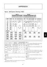
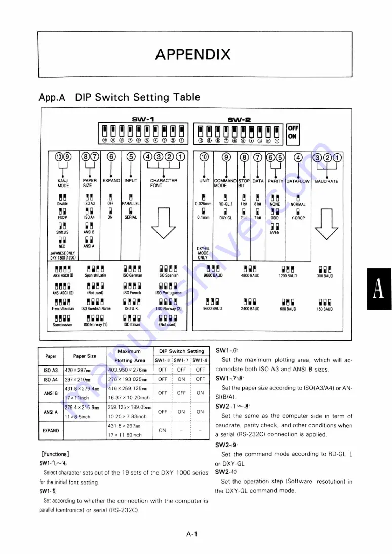
App.A DIP Switch Setting Table
Paper
Paper S ize
M a x im u m
D IP S w i t c h S e ttin g
P lo ttin g A re a
S W 1 -6
SW 1-7
SW 1-8
ISO A3
420 x 2 9 7 mm
4 0 3 .9 5 0 x 276m m
O FF
O FF
O FF
ISO A4
297 x 2 1 0mm
2 7 6 x 193.025mm
O F F
ON
O FF
ANSI B
4 3 1 .8 x 2 7 9 .4 m
m
1 7 x 1 1 inch
4 1 6 x 2 5 9 .125mm
1 6 .3 7 x 1 0 .2 0 in c h
O F F
O FF
ON
ANSI A
279.4 x 215.
9m
m
11 x 8.5inch
2 5 9 .1 2 5 x 1 9 9 .0 5 m
m
10. 2 0 x 7 . 8 3 inch
O FF
ON
ON
EXPAND
431. 8 x 297 mm
17 x 11. 69 inch
ON
-
[Functions]
SW1-(1)~(4)
Select character sets out of the 19 sets of the DXY-1000 series
for the initial font setting
SW1-(5)
SW1-(6)
Set the maximum plotting area, which will ac
comodate both ISO A3 and ANSI B sizes
SW1-(7)(8)
Set the paper size according to ISO(A3/A4) or AN
SI(B/A).
S W 2 -(1)~ (8)
Set the same as the computer side in term of
baudrate, parity check, and other conditions when
a serial (RS-232C) connection is applied.
SW2-(9)
Set the command mode according to RD-GL I
or DXY-GL
SW2-(10)
Set the operation step (Software resol ution) in
the DXY-GL command mode.
Set according to whether the connection with the computer is
parallel (centronics) or serial (RS-232C).
A-1
Summary of Contents for DXY-1100
Page 1: ...X Y PLOTTER DXY 1300 1200 1100 Roland DIGITAL GROUP ...
Page 2: ......
Page 3: ...X Y PLOTTER DXY 1300 1200 1100 COMMAND REFERENCE MANUAL c ...
Page 4: ......
Page 44: ......
Page 140: ......
Page 142: ......
Page 144: ......
Page 148: ......
Page 154: ......
Page 155: ......
Page 156: ...Roland DIGITAL GROUP ...

