58
Chapter 4 Engraving
4-4 Cutter Installation Method 1 (With Nose Unit)
2.
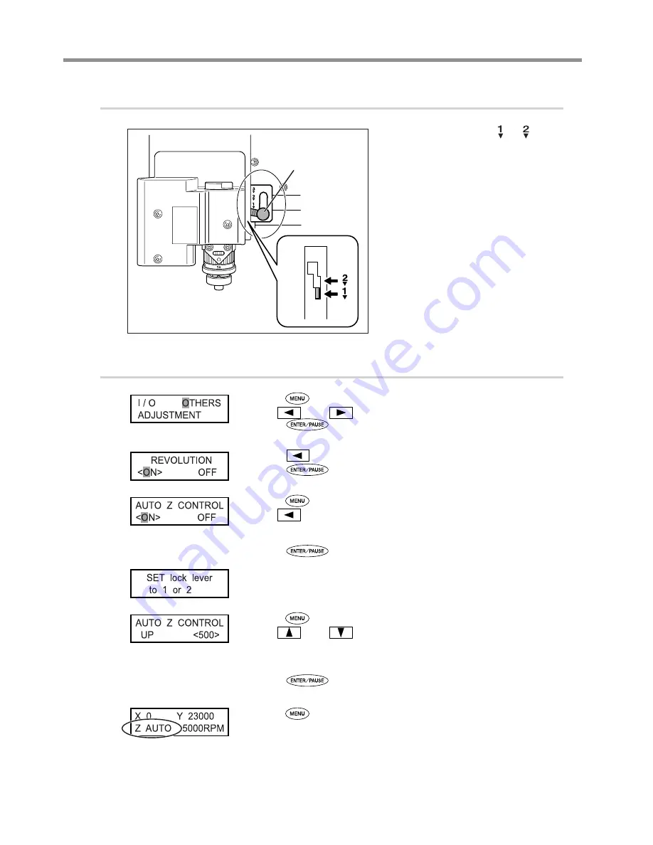
Set the lock lever.
Set the lock lever at the or posi-
tion.
For detailed information about the setting posi-
tion for the lock lever, refer to the page indicated
below.
P. 82, “The Position of the Lock Lever”
3.
Make the settings for spindle speed and Z-axis control.
Press
several times to display the screen shown at left.
Use
and
to select [OTHERS].
Press
.
Press
to select “ON.”
Press
to confirm.
Press
.
Use
to select “ON.”
The machine automatically determines the Z-axis origin during cutting according
to the height of the workpiece.
Press
to confirm.
The message shown at left is displayed for three seconds, and then the original
screen returns.
Press
.
Use
and
to select the value.
This makes the setting for the distance the cutter rises from the Z-axis origin point
during cutting (the cut-out amount). When making this setting, take into account
the shape of the workpiece and the time required for movement.
Press
to confirm.
Press
several times to return to the main screen.
The Z-axis coordinate display changes to “AUTO.”
Lock lever
Press down to lower
slightly.
Summary of Contents for EGX-350
Page 22: ...20...
Page 36: ...34 Chapter 2 Installation and Setup 2 4 Selecting the Language Switch off the power switch OFF...
Page 38: ...36...
Page 96: ...94...
Page 108: ...106...
Page 114: ...Chapter 8 Appendix 112 8 4 Main Unit Specification Dimensions of Outline Unit mm...
Page 119: ...117...
Page 120: ...118...
Page 121: ...119...
Page 122: ...120...
Page 123: ......
Page 124: ...R7 120615...


