background image

5-8 If an Error Message Appears

109

Chapter 5 What to Do If

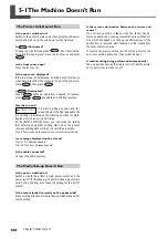
[TEMPERATURE IS TOO HIGH **

°

C]

The temperature of the location where the machine
is installed has risen above the ambient tempera-
ture at which the machine can operate.

Operation cannot be continued. Switch off the sub power.
The displayed temperature is room temperature of installa-
tion location now. Bring the installed location to a tem-
perature at which operation is possible (20 to 32

°

C) and

allow the machine to come to room temperature, then turn
on the power.

[TEMPERATURE IS TOO LOW **

°

C]

The temperature of the location where the machine
is installed has fallen below the ambient tempera-
ture at which the machine can operate.

Operation cannot be continued. Switch off the sub power.
The displayed temperature is room temperature of installa-
tion location now. Bring the installed location to a tem-
perature at which operation is possible (20 to 32

°

C) and

allow the machine to come to room temperature, then turn
on the power.

[WRONG CARTRIDGE]

A cartridge that cannot be used was installed.

Remove the cartridge to clear the error. Use a cartridge of
the specified type.

A cartridge was inserted with too much force.

Remove the cartridge to clear the error.   Insert and remove
cartridges slowly and gently, one at a time.

Summary of Contents for Hi-Fi Express FP-740

Page 1: ...al and the specifications of this product are subject to change without notice The operation manual and the product have been prepared and tested as much as possible If you find any misprint or error please inform us Roland DG Corp assumes no responsibility for any direct or indirect loss or damage which may occur through use of this product regardless of any failure to perform on the part of this...

Page 2: ...it will not fit the outlet have the proper outlet installed by a qualified electrician Check with qualified electrician or service personnel if the grounding instructions are not completely understood or if in doubt as to whether the tool is properly grounded Use only 3 wire extension cords that have 3 prong grounding plugs and 3 pole receptacles that accept the tool s plug Repair or replace damag...

Page 3: ...aning 52 Care and Maintenance of the Print Heads 53 3 2 When Head Cleaning Is Not Effective 54 Performing More Powerful Cleaning 54 When Powerful Cleaning Is Not Effective 55 3 3 Cleaning the Heads Using the Cleaning Kit 56 When the Cleaning Kit Becomes Necessary 56 How to Perform Cleaning 56 3 4 Replacing Consumable Parts 60 Replacing the Wipers 60 Replacing the Separating Knife 63 3 5 When Not i...

Page 4: ...Screen 89 Verifying the Setting for the Amount Remaining Every Time the Media Is Changed 89 Printing the Amount of Remaining Media 90 4 8Viewing System Information 91 Viewing the Serial Number Firmware Version and Other Information 91 Printing a System Report 91 4 9 Performing Maintenance 92 Draining Ink and Performing Internal Washing 92 Draining Ink Remaining Inside the Machine 92 4 10 Menu List...

Page 5: ... trademarks of their respective holders http www rolanddg com Chapter 6 Specifications 111 6 1 Usable Media 112 Conditions for Usable Media 112 6 2 Printing Area 113 Printing Area and Margins 113 6 3 Locations of the Power Rating and Serial Number Labels 114 Printer 114 Take up unit 114 6 4 Specifications 115 ...

Page 6: ... determined by the design contained within the triangle The symbol at left means danger of electrocution The symbol alerts the user to items that must never be carried out are forbidden The specific thing that must not be done is indicated by the design contained within the circle The symbol at left means the unit must never be disassembled The symbol alerts the user to things that must be carried...

Page 7: ...trical shock or injury Entrust repairs to a trained service tech nician CAUTION Exercise caution to avoid being pinched or becoming caught Inadvertent contact with certain areas may cause the hand or fingers to be pinched or become caught Use care when performing operations Never attempt operation while wearing a necktie necklace or loose clothing Bind long hair securely Such items may become caug...

Page 8: ...a damaged article may result in fire or electrical shock WARNING When using an extension cord or power strip use one that adequately satisfies the machine s ratings for voltage frequency and current Use of multiple electrical loads on a single elec trical outlet or of a lengthy extension cord may cause fire Connect to ground This can prevent fire or electrical shock due to current leakage in the e...

Page 9: ...the power cord plug and electrical outlet Never place any object on top or subject to damage Never bend or twist with undue force Never pull with undue force Never bundle bind or roll up Never allow to get wet Never make hot Dust may cause fire ...

Page 10: ...ess In the event of contact with the eyes immediately flush with water for at least 15 minutes If eye irritation continues seek treatment by a physician In the event of contact with skin immediately wash with soap If irritation or inflammation occur seek treat ment by a physician In the event of ingestion do not induce vomiting and immediately seek treatment by a physician Forcibly inducing vomiti...

Page 11: ...r accident in cluding tipover fall or collapse Be sure to anchor the stand to the floor If the machine should begin to topple a major accident may result including crushing of the appendages or the body CAUTION Handling roll media is an operation that must be performed by two persons or more and care must be taken to prevent falls Attempting to lift heavy media in a manner that taxes your strength...

Page 12: ...he meanings of these labels are as follows Be sure to heed their warnings Also never remove the labels or allow them to become obscured Caution Moving Print Heads The print heads inside the cover move at high speed and pose a hazard Never insert the hand or fingers into the gap Warning Labels ...

Page 13: ... sur la maison tous les meubles et même les animaux domestiques ATTENTION PRUDENCE À propos des symboles Le symbole attire l attention de l utilisateur sur les instructions importantes ou les avertissements Le sens précis du symbole est déterminé par le dessin à l intérieur du triangle Le symbole à gauche signifie danger d électrocution Le symbole avertit l utilisateur de ce qu il ne doit pas fair...

Page 14: ...choc électrique ou des blessures Confier les réparations à un technicien ayant la formation requise L utilisation incorrecte peut causer des blessures PRUDENCE Faire preuve de prudence pour éviter l écrasement ou le coincement La main ou les doigts peuvent être écrasés ou coincés s ils entrent en contact avec certaines surfaces par inadvertance Faire preuve de pru dence pendant l utilisation de l ...

Page 15: ...t la prise électrique correctement et avec soin Ne jamais utiliser un article endommagé car cela pourrait causer un incendie ou un choc électrique Si une rallonge ou une bande d alimentation électrique sont utilisées s assurer qu elles correspondent aux caractéristiques de l appareil tension fréquence et courant L utilisation de plusieurs charges électriques sur une prise unique ou une longue rall...

Page 16: ...sur la fiche ou sur la prise car cela risque de les endommager Ne jamais plier ni tordre le câble avec une force excessive Ne jamais tirer sur le câble ou la fiche avec une force excessive Ne jamais plier ni enrouler le câble Ne jamais laisser l eau toucher le câble la fiche ou la prise Ne jamais chauffer le câble la fiche ou la prise La poussière peut causer un incendie ...

Page 17: ...n ou de trouble physique En cas de contact avec les yeux rincer immédiatement et abondamment à l eau courante pendant au moins 15 minutes Si les yeux sont toujours irrités consulter un médecin En cas de contact avec la peau laver immédiatement à l eau et au savon En cas d irritation ou d inflammation de la peau consulter un médecin En cas d ingestion ne pas provoquer le vomissement et demander imm...

Page 18: ...uer un accident grave comme le renversement la chute ou l écrasement S assurer d ancrer la base de l appareil au sol Si l appareil devait commencer à basculer il s ensuivrait un accident grave par exemple l écrasement de membres ou du corps PRUDENCE La manutention du support en rouleau doit être faite par deux personnes ou plus et il faut prendre des précautions pour éviter les chutes Tenter de so...

Page 19: ...ion des vignettes est donnée ci dessous Respecter les avertissements Ne jamais retirer les vignettes et ne pas les laisser s encrasser Attention Têtes d impression mobiles Les têtes d impression sous le couvercle se déplacent à haute vitesse et représentent un danger Ne jamais insérer la main ou les doigts dans l ouverture Vignettes d avertissement ...

Page 20: ... operating conditions The Print Heads Are Delicate Never needlessly touch or allow media to scrape them Failure to handle with care may cause damage The print heads may be damaged if allowed to dry out The machine prevents desiccation automatically but improper operation may render this feature inoperative Operate properly as specified in this manual Never allow the machine to stand with an ink ca...

Page 21: ... to Impact or Attempt to Disassemble Never drop or shake forcefully The impact may rupture the internal pouch and cause the ink to leak Never attempt to disassemble Never attempt to refill the ink If ink gets on your hands or clothing wash it off as soon as possible Removal may become difficult if allowed to stand Storage Store unopened in a well ventilated location at a temperature of 20 to 40 C ...

Page 22: ...20 ...

Page 23: ...21 Chapter 1 Introduction ...

Page 24: ... when you load media Front Cover Be sure to close this when you perform printing Drain Bottle This collects drained ink and other such fluids Discard any collected fluid before it overflows Main Power Switch Left Side Cover You remove this when you perform maintenance Right Side Cover You remove this when you perform maintenance Ethernet Connector This is used to connect the printer to a network P...

Page 25: ...ide for positioning the right edge of the media Print head Carriage The print heads are inside this Grit Rollers These rollers feed out media toward the front of the machine Pinch Rollers These clamp the media when the loading lever is pulled back toward you Platen This is the path over which the media passes A suction fan that keeps the media from coming loose Knife Guide The separating knife pas...

Page 26: ...this when you want to set the print start position This lights up when the set has been made ENTER Key You use this for such tasks as enabling setting values BUSY Light This lights up during printing and other such operations Cursor Keys You use these to select set tings for menu items to move the media and for other such operations MENU Key You press this to enter the menus for various settings C...

Page 27: ...m MANUAL Switch You use this when you want to operate the take up unit manually Take up Unit This takes up media AUTO Switch This makes the direction of rotation for take up during printing change automati cally Mirror Sensor Main Power Switch This switch take up on and off ...

Page 28: ...26 ...

Page 29: ...27 Chapter 2 Operation ...

Page 30: ...nplug the power cord suddenly while operation is in progress Doing so may damage the print heads Be sure to first switch off the sub power If the main power is accidental switched off immediately turn the power back on Switching the Sub Power On Close the front cover and press the sub power switch Switching the Sub Power Off Press and hold the sub power switch for one second or longer The power ta...

Page 31: ...e time of the shift to the sleep mode You can also switch off the power saving feature p 86 Setting the Interval until Activation of the Sleep Mode p 86 Deactivating the Sleep Mode When the machine is in the sleep mode the POWER light flashes slowly Using the control panel or performing operations such as sending printing data from the computer when media is loaded restore the machine to its norma...

Page 32: ...ury handle with care CAUTION Never load media that weights more than 20 kg 44 lb The machine may fail to withstand the weight and tip over or cause the media to fall 1 Mounting the paper tube of take up unit Pull out the stopper Align the flange with the groove on the shaft and press in all the way Insert the stopper Follow steps and to mount the flange for the arm as well Stopper Stopper Flange A...

Page 33: ... Operation Insert the reinforcement pipe into the paper tube Mount the paper tube to flange Move the arm to match the length of the paper tube Tighten the mounting screw securely Paper tube Reinforcement pipe Flange Arm Mounting screw Paper tube ...

Page 34: ...ront cover Line up with the core diameter of the loaded roll media and refit the left and right hand media flanges Remove the stopper Attach the stopper Line up the ridges and grooves Stopper Front cover Media flange Line up the ridges and grooves Media flange 2 in 3 in Stopper Remove the media flange ...

Page 35: ...fit it into the roll media Reinforcement pipe When roll media sag severely use the reinforcement pipe in serted into the roll media After use remove the reinforcement pipe from the paper tube End caps If the left or right edges of the media strike the media flanges with force affecting media feed then use the end caps instead of the media flanges Media flange Roll media Media flange Roll media Rei...

Page 36: ...xt to the paper tube Hold the media at the center and slowly pull it out being sure to keep it straight Set the AUTO switch off Loading the media Load the media straight Correct take up is difficult if the fed out media becomes slack or crooked POWER BACKWARD FORWARD BACKWARD FORWARD AUTO MANUAL ON OFF OFF Correct Incorrect Entire media stretched taut Media is slack Media is crooked ...

Page 37: ...ure with tape at the two edges and center First fasten the center in place then fasten the edges Take up with outward curl Take up with inward curl Pull back the loading lever to secure the media in place Press to pull out the media Ensure a certain amount of slack as shown in the figure Loading lever Paper tube Adhesive tape Paper tube Adhesive tape Fasten first Fasten first ...

Page 38: ... the media Take up the media for one turn or more Take up with outward curl Take up with inward curl 4 Adjust the take up unit to match the width of the media Press to pull out the media Ensure a certain amount of slack as shown in the figure Take up one turn or more Take up one turn or more ...

Page 39: ... 3 millimeters Tighten the knobs at the back Make sure the slider units do not become titled as you do this Pass the tracking shafts through the looped media and fit then into the grooves of slider unit right and left Attach the stoppers at both ends 1 to 3 mm 1 to 3 mm Slider units Media Stopper Tracking shafts Slider unit Slider unit Knob Stopper Slider unit OK Not OK OK Not OK OK Not OK Media ...

Page 40: ...ng for the AUTO switch 6 Set the media clamps and close the front cover Set the media clamps The media clamps are magnetic Close the front cover Press Media having an outward curl Media having an inward curl Engage this area of the media clamp onto the edge of the platen Line up the hole with the end of the media ...

Page 41: ...ge portion where the paper tube is fitted is shown below Make sure the margin described below is present between each flange and the edge of the media Attempting to take up media when no margin is present may cause the media to touch the flange and result in faulty take up Important Notes on the MediaTake up Systems Never attempt any operation that pulls the media by using Doing so may activate a ...

Page 42: ...ry may result if attempted by one person without assistance CAUTION When the reinforcement pipe is inserted into the paper tube do not angle the paper tube The reinforcement pipe may protrude from the paper tube and cause injury 1 Cut off the media Set the AUTO switch off Close the front cover Make sure lights up Hold down for one second or longer The media is cut off here Front cover ...

Page 43: ...pipe from the paper tube Cut off Operations Do not cut off the media while take up is in progress Take up quits as soon as the media is cut off Be especially careful when you re printing more than one page Give Attention to Media Composition For some types of media cutoff is not possible Some types of media may remain on the platen after cutoff If the media remains on the platen remove it by hand ...

Page 44: ...chine does not run when the front cover is open Also never open it when printing is in progress Doing so interrupts printing Data from the computer is not accepted when is dark does not light up when media is loaded incorrectly Data from the computer is not accepted when you are not at the top menu Adjusting Head Height to Match MediaThickness Depending on the media media may wrinkle or come loose...

Page 45: ...al printing If problems such as dot drop out are found clean the print heads How to Perform a PrintingTest Holding down for one second or longer prints a test pat tern You can print the test pattern where you want by using to move the print heads then pressing The front cover may be open during movement but be sure to close it before you press Printing test A B C D Dot drop out ...

Page 46: ...ps are displayed Press Cleaning starts When it finishes the screen shown in the figure appears again Press Press to go back to the original screen Perform a printing test again to make sure the dot drop out has been corrected If the problem persists try performing cleaning a second time If the problem doesn t go away even after performing cleaning two or three times then try cleaning using a diffe...

Page 47: ...what from the actual amount remaining Also the displayed information may differ from the actual amount remaining if you insert a party used ink cartridge or change cartridges while the power is off BK CY MG YE CY BK CY MG YE BK Displays the amount of ink remaining in each of the ink cartridges Amount remaining 50 to 100 Lighted Lighted Dark Lighted Flashing Flashing No ink Amount remaining 50 or l...

Page 48: ...de to the amount of remaining ink which may differ somewhat from the actual amount remaining Also the displayed information may differ from the actual amount remaining if you insert a party used ink cartridge or change cartridges while the power is off MENU INK REMAINING 1 2 3 4 5 6 7 8 W 1839 mm SETUP SHEET 1 2 3 4 5 6 7 8 Much Little Amount of ink remaining Flashing display Cartridge slot number...

Page 49: ... beep sounds and printing pauses When you replace a cartridge with a new one printing resumes after from five to ten minutes but a difference in color may be apparent at the seam between the locations where printing paused and resumed Be sure to replace cartridges before ink runs out Important Notes on Replacing Cartridges Be sure to replace with an item of identical type Never mix items of differ...

Page 50: ...48 ...

Page 51: ...49 Chapter 3 Maintenance and Adjustment ...

Page 52: ...DRAIN BOTTLE menu item Press Press several times Press Press Press Press Press Preparations are complete when this screen appears 2 Empty the bottle by discarding the discharged fluid CAUTION Before you detach the drain bottle be sure to wait for the screen to display EMPTY DRAIN BOTTLE Failing to follow this procedure may cause discharged fluid to flow out of the tube and spill soiling your hands...

Page 53: ...ispose of discharged fluid properly in accordance with the laws in effect in your locale Discharged fluid is flammable and contains toxic ingredients Do not attempt to incinerate discharged fluid or discard it with ordinary trash Also do not dispose of it in sewer systems rivers or streams Doing so may have an adverse impact on the environment MAINTENANCE DRAIN BOTTLE RESET DRAIN COUNT W 1839 mm S...

Page 54: ... by neutral detergent diluted with water then wrung dry Never attempt to oil or lubricate the machine Grit rollers Remove buildup of media and other ma terial using a brush Never use a metal brush Pinch rollers Periodically wipe away any grime Fail ure to clean properly may result in the transfer of grime to the surface of me dia Clean this area especially well Any soil ing present here may impair...

Page 55: ...problems such as dot drop out occur frequently and are not corrected by the machine s head cleaning feature clean the heads using the cleaning kit Such cleaning can be effective when carried out periodically according to the frequency of use p 56 Cleaning the Heads Using the Cleaning Kit The print heads are components that wear out Periodic replacement is required with the frequency of replace men...

Page 56: ...apable of correct printing 1 Choose medium cleaning or powerful cleaning Press Medium Press once Powerful Press twice 2 Specify the head group to clean Press Use to choose the group of a head that is not to be cleaned Use to get rid of the group display Repeat this procedure to display the groups of only the heads that require cleaning Cleaning is performed only for the heads whose groups are disp...

Page 57: ...s Not Effective If problems such as dot drop out persist even after you have performed powerful cleaning several times then use the cleaning kit to clean the heads Such cleaning can be effective when carried out periodically according to the fre quency of use p 56 Cleaning the Heads Using the Cleaning Kit ...

Page 58: ...urchase them from your authorized Roland DG Corp dealer How to Perform Cleaning Important Notes onThis Procedure To prevent the heads from drying out finish this procedure in 30 minutes or less A warning beep sounds after 30 minutes At this time stop work attach the right side cover and press When the head protection operation finishes restart the procedure from the beginning Never use any impleme...

Page 59: ... Preparations are complete when this screen appears 2 Remove the left and right side covers and maintenance cover Remove the left and right side covers Remove the maintenance cover Touch the location shown in the figure to discharge any static electricity MENU SUB MENU SUB MENU MAINTENANCE MAINTENANCE CLEANING FINISHED Screw Screw Screw Screw Side cover Maintenance cover Side cover ...

Page 60: ...reful to clean away any fibrous dust lint Clean in the sequence shown in the figure below Cleaning stick Be sure to clean using one of the included cleaning sticks Never touch the nozzle surface Clean only the metal frame Gently stroke the sponge Never rub with force Area to clean Area to clean Area to clean Area to clean Area to clean ...

Page 61: ...o install Press After the processing to quit the manual cleaning mode ends the screen shown in the figure appears Press Press to go back to the original screen 5 Perform a printing test to verify the results of the procedure Perform a printing test to check the results Perform automatic cleaning several times as required p 43 Printing Test and Cleaning MAINTENANCE CLEANING W 1839 mm SETUP SHEET Sc...

Page 62: ...ning beep sounds after 30 minutes At this time stop work attach the right side cover and press When the head protection operation finishes restart the procedure from the beginning CAUTION Be sure to perform operations as specified by these instructions and never touch any area not specified in the instructions Sudden movement of the machine may cause injury 1 Display the REPLACEWIPER menu Press Pr...

Page 63: ...t side cover Touch the location shown in the figure to discharge any static electricity 3 Replace the wipers Use the included tweezers Detach the old wipers Detach the hook and pull up and out Insert the new wipers Attach the hook Hook Hook Right side cover Felt surface toward the rear Rubber surface toward the front ...

Page 64: ... the right side cover Press After the processing to quit the REPLACE WIPER menu ends the screen shown in the figure appears Press Press to go back to the original screen Perform a printing test to verify the results of the procedure p 43 Printing Test and Cleaning MAINTENANCE REPLACE WIPER W 1839 mm SETUP SHEET Side cover Hook NOW PROCESSING ...

Page 65: ...keep the print heads from drying out complete the operation within three minutes After three minutes a warning beep sounds Complete the operation quickly and when finished press 1 Enter the blade replacement mode Press Press several times Press Press several times Press Preparations are complete when this screen appears 2 Replace the separating knife Open the front cover Remove the separating knif...

Page 66: ... Chapter 3 Maintenance and Adjustment Slowly insert it into the groove Tighten the screw Take care to ensure that the knife does not slip out of position at this time 3 Quit the REPLACE KNIFE menu Close the front cover and press Screw ...

Page 67: ...at a ConstantTemperature and Relative Humidity Even when the machine is not in use keep it at a temperature of 5 to 40 C 41 to 104 F and a relative humidity of 20 to 80 with no condensation Temperatures that are too high may degrade the ink and cause malfunction Tempera tures that are too low may cause the ink to freeze and damage the heads If the MachineWill Be Out of Use for a Month or Longer If...

Page 68: ...66 ...

Page 69: ...67 Chapter 4 Feature Reference ...

Page 70: ... Finishes Procedure Press Hold down for one second or longer Stop sending printing data from the computer Description pauses printing Pressing a second time here resumes printing but a horizontal stripe is produced at the location where printing was stopped We do not recommend resuming printing ...

Page 71: ...ds Press If the front cover is open then close it Press Description You can shift the printing position to the left by using Note however that this setting must be made for each individual page When the printing of one page finishes the left right positioning returns to its default value When the position has been set lights up and the screen displays the printable width at the set position This f...

Page 72: ...ther the settings you ve made at the menus shown below and save them as a preset Required menu items for using media whose width cannot be detected automatically SHEET TYPE SHEET WIDTH SHEET POS p 80 Loading Media Whose Width Cannot Be Detected Automatically Menu items for adjustments to match the thickness ADJUST BI DIR CALIBRATION p 73 Correcting for Misalignment in Bidirectional Printing p 75 C...

Page 73: ...rt printing press once more and redo the preparations for printing Assigning a Name to a Preset Procedure Press Press Press twice Press Use to select any one from NAME1 to NAME8 Press Use to enter a character Press Use to enter the next character Enter the following characters in the same way When you re finished entering text press Press Press to go back to the original screen Description This as...

Page 74: ... heads When you are using such media adjust the head height to HIGH Note that the height of the heads cannot be determined by just the thickness of the media When the height is set to LOW the media clamps cannot be used Except in special cases the LOW setting should never be used Doing so may cause the heads to strike the clamps and become damaged Default Setting HEAD HEIGHT MIDDLE Height adjustme...

Page 75: ...ress Press Press to start printing 3 Read the correction values from the test pattern 4 Enter the correction values that you read Press Press Use to set the correction values Press to enable the setting MENU ADJUST BI DIR ADJUST BI DIR TEST PRINT ADJUST BI DIR SIMPLE SETTING SIMPLE SETTING 0 1 Simple Simple Test pattern Choose the value that produces the least misalignment Current correction value...

Page 76: ...orm printing during both their outbound pass and return pass offers the advantage of being fast but subtle misalignment occurs between the outbound and return passes The procedure to correct this and eliminate misalignment is bidirectional correction This misalignment varies according to the head height and the thickness of the media so we recommend performing correction to match the media you re ...

Page 77: ...int a test pattern Press Press Press Press twice Press Press to start printing 3 Read the correction values from the test pattern MENU ADJUST BI DIR DETAIL SETTING TEST PRINT ADJUST BI DIR DETAIL SETTING Test pattern SETTING NO Head number Correction value Current correction value Choose the value that produces the least misalignment In this case choose 3 1 2 H1 1 H2 2 H3 6 H4 3 1 2 H5 2 H6 8 H7 9...

Page 78: ...for SETTING NO 1 Press Press Use to select Use to set the correction values Press for finish making the settings for SETTING NO 2 Press Press Use to select Use to set the correction values Press for finish making the settings for SETTING NO 3 Press H1 H2 H3 0 0 0 H4 H5 H6 0 0 0 H7 H8 0 0 H1 H2 H3 0 0 0 H4 H5 H6 0 0 0 H7 H8 0 0 DETAIL SETTING SETTING NO 2 DETAIL SETTING SETTING NO 3 DETAIL SETTING ...

Page 79: ...the original screen Press Press to go back to the original screen Description This corrects for each head the minute misalignment that occurs in the bidirectional printing mode When further correction is required such as when adjustment made using SIMPLE SETTING do not enhance printing use DETAIL SETTING to make corrections for each head W 1839 mm SETUP SHEET H1 H2 H3 0 0 0 H4 H5 H6 0 0 0 H7 H8 0 ...

Page 80: ...nting 2 Check the test pattern you printed 3 Enter the correction value Press Press Use to make the setting for the correction value Press to enable the setting 4 Go back to the original screen Press Press to go back to the original screen MENU CALIBRATION CALIBRATION TEST PRINT W 1839 mm SETUP SHEET SETTING 0 00 0 15 Gap present Correct results Overlap Reduce the value 0 Increase the value Test p...

Page 81: ...e a number of times to find the optimize value Printing this test pattern using parameters identical to those for actual printing Also using material such as media scraps that have passed through the printer may not yield correct results Note however that you can also make this setting on the computer by for example choosing the media type in the RIP program you are using Use this feature when you...

Page 82: ... Press Press several times Press twice Use to select CLEAR Press to enable the setting Press Press to go back to the original screen 2 Make the setting for the media width Press Press several times Press Press Press Use to enter the media width Press to enable the setting Press to go back to the previous screen 3 Make the setting for the location of the right edge of the media Press Press The prin...

Page 83: ...a is present To quit making settings at the SHEET POS menu use to select CAN CEL then close the front cover and press Note that to keep the heads from drying out the SHEET POS menu ends automatically after a certain interval even if you re still making settings there The settings for the media width and start position made here are effective only when SHEET TYPE is set to CLEAR Selecting OPAQUE di...

Page 84: ...ss Use to set the value Press to enable the setting Press Press to go back to the original screen Description The platen uses suction to grip the media and keep it stable When media comes loose from the platen because it is warped or wrinkled increasing the suction force may help correct the problem Conversely when the media is flimsy and cannot move smoothly reducing the suction force may help Wh...

Page 85: ... head movement to the printing data Movement is limited to the minimum amount neces sary and this can be expected to yield the fastest printing Note however that because the speed of media movement is no longer constant colors may be uneven FULL makes the speed of media movement constant at all times Default Setting FULL WIDTH S FULL Keeping Media from Being Soiled by Ink Drips Procedure Press Pre...

Page 86: ...es The ink buildup is removed as printing is performed When this is set to PAGE automatic cleaning is performed every time before printing starts When this is set to a value from 10 min to 990 min automatic cleaning is performed when the cumulative printing time reaches the value you set here When this is set to NONE no automatic cleaning is performed Using this feature results in longer printing ...

Page 87: ...tridge has been replaced When this is set to CONT printing starts and continues until the ink remaining inside the machine is used up Regardless of the setting made for this menu item we recommend replacing the ink cartridge immediately whenever a cartridge becomes empty Default Setting EMPTY MODE STOP Expanding the Printing Area by Reducing the Margins Procedure Press Press several times Press Pr...

Page 88: ...use the margins are reduced the media clamps may be overprinted Default Setting SIDE MARGIN 20 mm Setting the Interval until Activation of the Sleep Mode Procedure Press Press several times Press Press several times Press twice Use to make the setting Press to enable the setting Press Press to go back to the original screen Default Setting INTERVAL 30min Deactivating the Sleep Mode Procedure Press...

Page 89: ... power Use to select the display menu language Press Use to select the measurement unit for length Press Description This sets the language and units of measurement displayed on the printer s screen Default Setting MENU LANGUAGE ENGLISH LENGTH UNIT mm Returning All Settings toTheir InitialValues Procedure Press Press several times Press Press several times Press to execute W 1839 mm SETUP SHEET SL...

Page 90: ...e Printer Operates 88 Chapter 4 Feature Reference Description This menu returns all settings to the same as their factory defaults However the settings for LANGUAGE and LENGTH UNIT are not returned to the factory defaults ...

Page 91: ...me flashes on the screen The amount of media remaining is not updated automatically when you change the media Redo the setting whenever you change the media You can also make the setting to display this menu automatically whenever you change the media See the next section Verifying the Setting for the Amount Remaining Every Time the Media Is Changed The remaining amount that is displayed is only a...

Page 92: ... TYPE is set to CLEAR then SHEET REMAIN is not displayed automatically regardless of the setting for AUTO DISPLAY Default Setting AUTO DISPLAY DISABLE Printing the Amount of Remaining Media Procedure Press Press Press Press to perform printing Press Press to go back to the original screen Description This prints the amount of media remaining that is displayed at the top menu You use this when you ...

Page 93: ...n view the following information MODEL model name SERIAL NO serial number INK ink type FIRMWARE firmware version Printing a System Report Procedure Press Press several times Press Press several times Press to start printing Press Press to go back to the original screen Description This prints system information including a list of setting values MENU SYSTEM INFO SYSTEM INFO SERIAL NO SERIAL NO ZS0...

Page 94: ...s to carry out the procedure After finishing washing the sub power is switched off You do not need to carry this out as part of your daily maintenance activities Draining Ink Remaining Inside the Machine Procedure Press Press several times Press Press twice Press Press Press to execute Description This removes ink inside the printer as a preliminary procedure for performing maintenance The screen ...

Page 95: ...E2 To the SHEET REMAIN menu To the NAME menu LOAD NAME4 LOAD NAME6 To the NAME8 menu To the NAME1 menu SAVE NAME1 SAVE NAME2 SAVE NAME4 SAVE NAME6 To the NAME8 menu To the NAME1 menu Continue Continue Continue Press LOAD NAME3 LOAD NAME5 LOAD NAME7 LOAD NAME8 SAVE NAME3 SAVE NAME5 SAVE NAME7 SAVE NAME8 p 70 p 71 ...

Page 96: ...ETTING CALIBRATION TEST PRINT SETTING 0 00 0 00 To the SETTING menu To the TEST PRINT menu Continue To the NAME8 menu DETAIL SETTING SETTING NO 2 DETAIL SETTING SETTING NO 3 DETAIL SETTING SETTING NO 4 H4 H5 H6 0 0 0 H1 H2 H3 0 0 0 H7 H8 0 0 H4 H5 H6 0 0 0 H1 H2 H3 0 0 0 H7 H8 0 0 H4 H5 H6 0 0 0 H1 H2 H3 0 0 0 H7 H8 0 0 H4 H5 H6 0 0 0 H1 H2 H3 0 0 0 H7 H8 0 0 NAME NAME1 NAME NAME2 NAME NAME4 NAME ...

Page 97: ...TERVAL OFF OFF INK CONTROL PUMP UP INK CONTROL HEAD WASH SUB MENU SCAN INTERVAL To the DRAIN BOTTLE menu To the EMPTY MODE menu SIDE MARGIN 20 mm 20 mm Continue SUB MENU SIDE MARGIN Continue SUB MENU MAINTENANCE MAINTENANCE CLEANING SYSTEM INFO MODEL SYSTEM INFO INK SYSTEM INFO FIRMWARE MAINTENANCE REPLACE WIPER MAINTENANCE DRAIN BOTTLE MENU SYSTEM INFO MODEL FP 740 SYSTEM INFO SERIAL NO SERIAL NO...

Page 98: ...eference Continue SHEET REMAIN SET LENGTH MENU SHEET REMAIN SHEET REMAIN PRINT MEMO SET LENGTH 0 0 m 0 0 m To the AUTO DISPLAY menu To the PRINT MEMO menu SHEET REMAIN AUTO DISPLAY AUTO DISPLAY DISABLE DISABLE To the PRESET menu p 89 p 90 ...

Page 99: ...own and switch on the sub power LENGTH UNIT mm mm SETUP SHEET CLEANING NORMAL CL CLEANING MEDIUM CL To the POWERFUL CL menu To the NORMAL CL menu NORMAL CL ABCD MEDIUM CL ABCD CLEANING POWERFUL CL POWERFUL CL ABCD Press Hold down for one second or longer p 43 Head cleaning for all groups p 43 p 54 p 87 p 87 p 54 ...

Page 100: ...98 ...

Page 101: ...99 Chapter 5 What to Do If ...

Page 102: ...ata while an ink cartridge is empty p 85 Determining What Happens When an Ink Cartridge Is Empty Is a message displayed on the screen p 107 If a Message Appears p 108 If an Error Message Appears Is the cable connected Connect the cable securely The MediaTake up Doesn t Run Is the power switched on Switch on both the printer s main power switch and the power switch for the take up To perform take u...

Page 103: ...are not suitable for the type of media printing may be adversely affected Choose settings optimized to the media you re using p 70 Saving Optimized Media Settings As Preset Values p 71 Loading a Saved Preset Colors Are Unstable or Uneven Is the media wrinkled If the media is wrinkled and comes loose from the platen colors may be uneven or printing reduce may suffer p 105 Media Wrinkles or Shrinks ...

Page 104: ... during printing Buildup of fibrous dust lint around the heads Ink transferred to the heads due to rubbing against the media If this happens clean the heads using the cleaning kit We recommend carrying out periodic head cleaning p 56 Cleaning the Heads Using the Cleaning Kit Are the pinch rollers dirty Periodically clean the pinch rollers ...

Page 105: ... the media warped or wrinkled Many factors can cause warping or wrinkling Refer to the following and correct the problem p 105 Media Wrinkles or Shrinks or Feed Is Unstable Is the height of the print heads too low Try raising the heads higher Media may inevitably warp or wrinkle slightly so adjust the height of the heads to take this into account p 72 Adjusting Head Height to Match Media Thickness...

Page 106: ... factors can make media feed unstable Refer to the following and correct the problem p 105 Media Wrinkles or Shrinks or Feed Is Unstable The Media Is Not Straight Is the width of the media 710 millimeters or more Media cannot be rerolled straight when its width is less than 710 millimeters Use media measuring 710 millime ters or more ...

Page 107: ...a install the reinforcement pipe Also when storing media place it so that it will not sag under its own weight The Media Is Not Straight Is the media loaded and set up straight and securely Feed is not smooth when the media is not straight or tensioned unevenly on the left and right Reload the media Media Feed Is Not Smooth Do the media or the media flanges strike some other object Make sure the m...

Page 108: ...ot Move If the heads still do not move carry out the following emer gency response measure then contact your authorized Roland DG Corp dealer or Roland DG Corp service cen ter 1 Switch off the main power and detach the right side cover 2 Open the front cover 3 Gently move the print heads by hand as far as the standby position 4 Insert the cap unit tool into the hole at the bottom of the machine an...

Page 109: ... to LOW Using them may cause malfunc tion After verifying press INSTALL DRAIN BOTTLE Check whether the drain bottle is installed Install the drain bottle then press REMOVE CARTRIDGE Remove the ink cartridge indicated by the flashing number This message appears at times such as during head clean ing REMOVE CL LIQUID Remove the cleaning cartridge indicated by the flashing number This message appears...

Page 110: ... tension was applied to the media and additional action is necessary to recover from this state First move the loading lever to the rear and open the cover for the take up unit Adjust the media to create a small amount of slack then switch on the sub power PINCHROLL ERROR LOWER PINCHROLL was pressed without first lowering the pinch rollers Press any key to clear the error Pull back the loading lev...

Page 111: ...ISTOO LOW C The temperature of the location where the machine is installed has fallen below the ambient tempera ture at which the machine can operate Operation cannot be continued Switch off the sub power The displayed temperature is room temperature of installa tion location now Bring the installed location to a tem perature at which operation is possible 20 to 32 C and allow the machine to come ...

Page 112: ...110 ...

Page 113: ...111 Chapter 6 Specifications ...

Page 114: ...weight Maximum 20 kg 44 lb Other conditions Media such as the following cannot be used Media whose end is attached to the paper tube core Media which is severely warped or which has a strong tendency to reroll Media whose paper tube core is bent or crushed Media that bends under its own weight when loaded This machine cannot necessarily print every kind of media When selecting media be sure to car...

Page 115: ...nged by using 2 Margin length required by the media take up 3 Margin set automatically default value for media whose width is detectable Media Printing area Right margin 1 Left margin Approx 1200 mm 47 3 in 2 10 mm 0 4 in 3 Approx 20 mm 0 8 in 3 10 mm 0 4 in 3 Approx 20 mm 0 8 in 3 Media clamp Media clamp ...

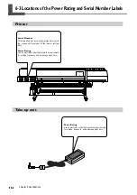
Page 116: ... is required when you seek maintenance servic ing or support Never peel off the label or let it get dirty Power Rating Use an electrical outlet that meets the requirements for voltage frequency and amperage given here Power Rating Use an electrical outlet that meets the requirements for voltage frequency and amperage given here ...

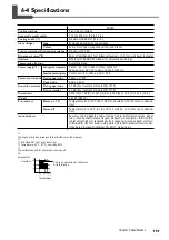
Page 117: ... 7779 40 dB A or less according to ISO 7779 3539 W x 758 D x 1307 H mm 139 4 W x 29 9 D x 51 5 H in 267 Kg 589 lb Temperature 20 to 32 C 68 to 89 6 F humidity 35 to 80 no condensa tion Temperature 5 to 40 C 41 to 104 F humidity 20 to 80 no condensa tion Power cords AC adapter cable clamps media reinforcement pipes paper tube tracking shafts media flanges stoppers media clamps drain bottle replacem...

Page 118: ...116 ...

Page 119: ......

Page 120: ...R2 070228 ...

Reviews:

Related manuals for Hi-Fi Express FP-740