44
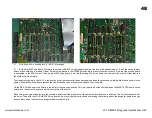
Step 3) Desolder the listed ICs, resistors and transistor and fit the supplied 40 pin IC sockets, resistors and links on the cpu board and both voice boards.
It is very important that this step is done correctly.
On the top side of the voice boards underneath the ICs (Integrated Circuits) that need to be removed are some fine tracks that will be damaged and
difficult to repair if all the solder is not removed correctly.
All the solder must be removed from all the 40 holes in the five large ICs and the 16 holes in the smaller ICs and the
pins free of the hole edges before the ICs are lifted out of the board.
All the CPU pins should be able to move freely in the holes which shows that they are not still soldered to the hole sides. The best way to achieve
this is with a good vacuum desoldering tool. A combination of a quality Solderwick and a hand vacuum can be used but you will need to take care
as these can cause damage to the board. The copper used in these older circuit boards is very soft at 300+ degrees and is very easily lifted from
the surface. A hand vacuum tool will jump and can damage tracks as it is triggered. If tracks are damaged they will need to be repaired before
proceeding to the next step. The best way to do this is with a fine enameled copper wire which is the same as is used to wind chokes or
transformers and can be found in most electronics parts stores.
JX-10 CPU Board
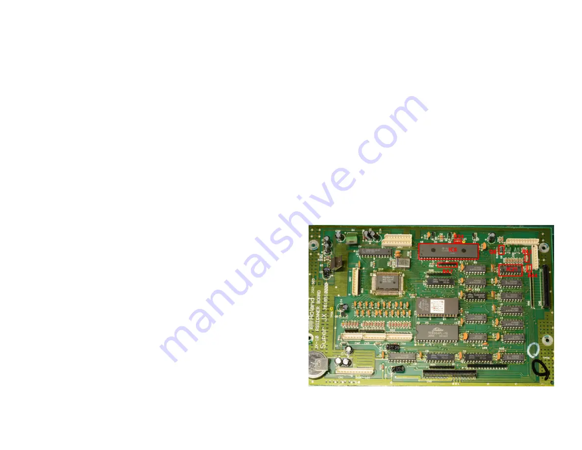
The following parts need to be removed from the cpu board.
1) In the JX-10 the following ICs and parts need to be removed from the
cpu board. IC8 (40 pin IC marked HD63B03), IC21 (16 pin IC marked
D7001) (this is present in only some MKS-70s), resistors R34, R43, R44,
the transistor Q8, and the Resistor Net RA7.
MKS-70 CPU Board
1) In the MKS-70 the following ICs and parts need to be removed from the
cpu board. IC8 (40 pin IC marked HD63B03), resistor R34 and the Resistor
Net RA7. In MKS-70 units with serial number 741300 and higher Q8, IC21
& R43, R44 will not be present on the CPU board. For boards that have
these parts they can be left in and do not need to be removed.
www.kiwitechnics.com
JX-10/MKS-70 Upgrade User Manual v100
Summary of Contents for Kiwitechnics KIWI-SJX
Page 1: ......
Page 6: ...Kiwi SJX JX 10 Flow Chart...
Page 7: ...Kiwi SJX MKS 70 Flow Chart...
Page 8: ...Kiwi SJX JX 10 Front Panel...
Page 9: ...Kiwi SJX MKS 70 Front Panel...
Page 89: ...89 www kiwitechnics com JX SJX Upgrade User Manual v100...


