46
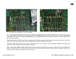
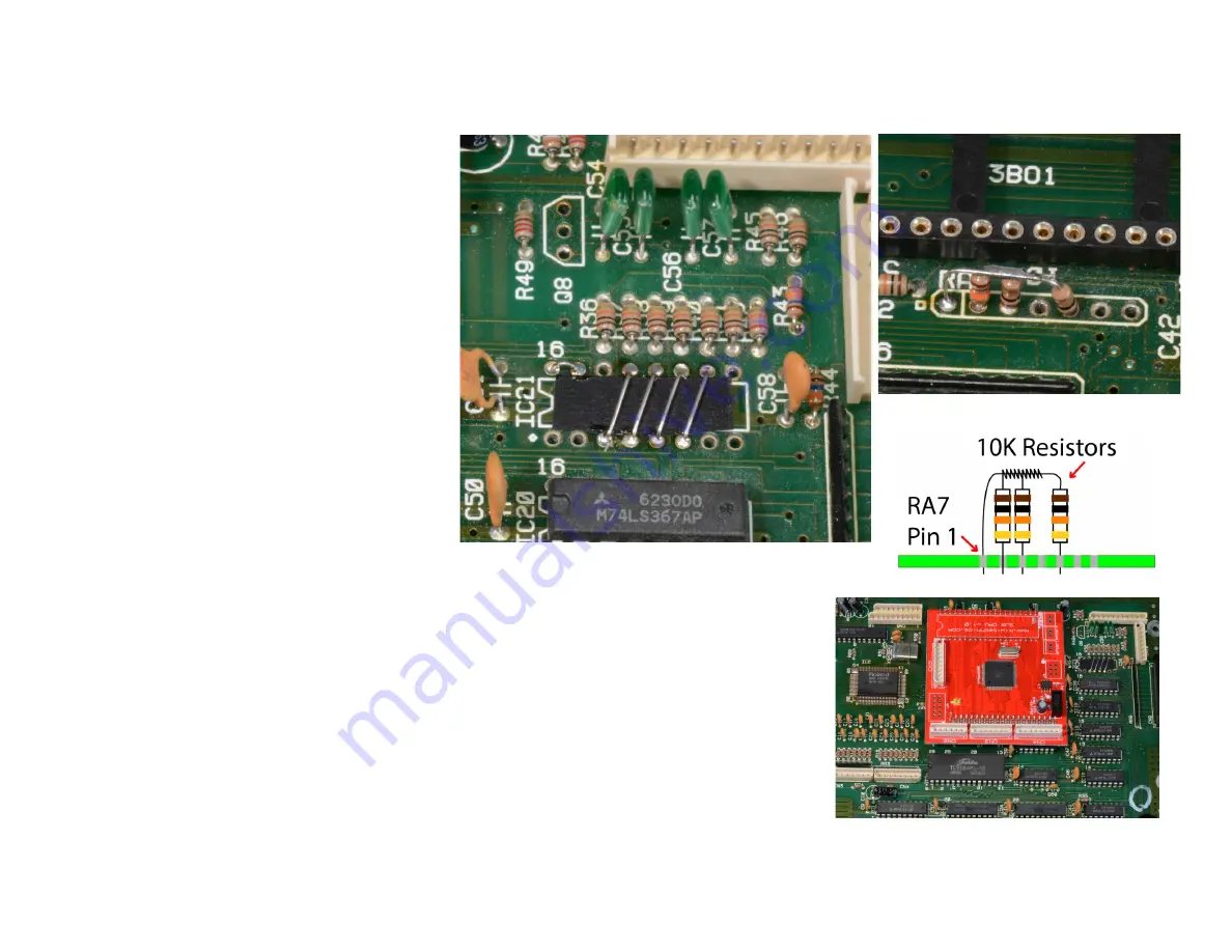
Here is a close up of the IC21 links in the JX-10
and the 16k resistors fitted to R43 & R44
positions and a close up of the RA7 10k
resistors for the MKS-70 and the JX-10.
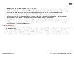
Link R34
– This is the resistor removed during
step 1 and this needs to be replaced with a link
in both the JX-10 & MKS-70.
Fit the three supplied 10k resistors. These go
between RA7 pin 1 and Pin 2, Pin 1 and 3 and
Pin 1 and Pin 5 as in the diagram. Pins 4, 6 & 7
should have nothing in them. Pin one has a
box around it on the circuit board.
3)
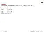
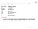
Bend down C40, C41 & C42 so they are not sitting straight up as this will stop the KiwiSJX
board from sitting fully in its socket. KiwiSJX CPU board. When fitting the upgrade boards into the
sockets make sure all the pins are in all the socket holes and press in half way. This will seat the
board into the holes. Then with the JX-10/MKS-70 board on a static free firm surface and something
firm directly under the daughter boards area you need to press down firmly until the daughter board
is seated fully. It is best to press one end at a time and then the sides until they are fully inserted. The
photo shows the board in the final position. The CPU daughter board fits into the socket marked IC8.
The notch printed on the KiwiSJX CPU board must match the notch printed onto the Jupiter
JX-10/MKS-70 Board (see photo). This is a tight fit and will require some force to insert correctly. Be
gentle but firm and support the board directly under the sockets as you press them in. The JX-10
version will have the keyboard sockets fitted.
www.kiwitechnics.com
JX-10/MKS-70 Upgrade User Manual v100
Summary of Contents for Kiwitechnics KIWI-SJX
Page 1: ......
Page 6: ...Kiwi SJX JX 10 Flow Chart...
Page 7: ...Kiwi SJX MKS 70 Flow Chart...
Page 8: ...Kiwi SJX JX 10 Front Panel...
Page 9: ...Kiwi SJX MKS 70 Front Panel...
Page 89: ...89 www kiwitechnics com JX SJX Upgrade User Manual v100...


