11
Feb,1999
MC-80
♦
♦
♦
♦
Caution:
•
When exiting the test mode and turning off the power, after
holding down [SHIFT] and [STOP] at the same time and
checking that display shows "The MC-80 may now be shut
down safety.", turn off the power for the MC-80.
•
Be sure to remove products, a floppy disk and a ZIP disk
for the test mode from customer’s MC-80.
♦
♦
♦
♦
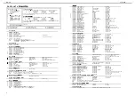
Details of the each test
TEST 1: VERSION
◆テストモードの注意
◆テストモードの注意
◆テストモードの注意
◆テストモードの注意
・ テストモードから抜けて電源を落とす場合は、
必ず
[SHIFT]+[STOP]
を押して、
"The MC-80 may now be
shut down safety."
の画面を確認した後、電源を落と
して下さい。
・ テストモード中で使用した製品やフロッピーディスク、
ZIP
ディスクをお客様の
MC-80
から外しておくことを
忘れないでください。
◆テストモードの詳細
◆テストモードの詳細
◆テストモードの詳細
◆テストモードの詳細
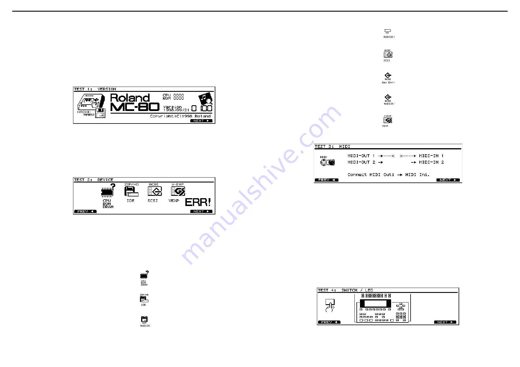
TEST 1: VERSION
1. Display shows the following with bleep.
• Checksum of CPU’s internal ROM and program ROM
• The version number and the date of making
* In TEST 2: DEVICE, when its test will be executed with the
ZIP Drive, Here insert the ZIP disk.
2. Check the version and checksum.Press [F6(NEXT)] to
advance to TEST 2: DEVICE.
TEST 2: DEVICE
1.
ビープ音が鳴るのと同時に、以下の内容が表示されます。
・
CPU
の内
ROM
および
PROGRAM ROM
のチェックサム
・プログラムのバージョンおよびリリースした日付
※
TEST 2: DEVICE
において
ZIP
ドライブを用いたテストを
行う場合、ここで
ZIP
ディスクを挿入してください。
2.
内容を確認した後、
[F6(NEXT)]
を押します。
TEST 2: DEVICE
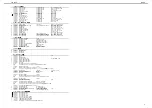
1. The following check runs automatically.
• CPU’s internal ROM, program ROM and DRAM
• Internal ZIP Drive or hard disk
• SCSI
• VE-GSPro
2. If all devices are working correctly, "OK" appears on
display and TEST 3: MIDI runs automatically.
* If "ERR!" appears on display, Check the following.
1.
以下のチェックを行います。
・
CPU
の内
ROM,PROGRAM ROM,D-RAM
・内蔵
ZIP
ドライブまたはハードディスク
・
SCSI
・
VE-GSPro
2.
全てのデバイスが正常に動作している場合は、
"OK"
が表
示され、自動的に
TEST 3: MIDI
へ進みます。
※ "ERR!"が表示された場合は、以下をチェックしてくださ
い。
CPU’s internal ROM or program ROM or DRAM is
defective.
Check IC3,IC5,IC2 on the MAIN BOARD.
CPU
の内
ROM,PROGRAM ROM,D-RAM
が不良です。
MAIN BOARD
の
IC3,IC5,IC2
をチェックしてください。
Install ZIP-INT-1A or HDP-88 in the MC-80.
ZIP-INT-1A
または
HDP-88
を
MC-80
に内蔵してくださ
い。
Insert a formatted ZIP disk into ZIP-INT-1A.
ZIP-INT-1A
にフォーマット済みの
ZIP
ディスクを挿入
してください。
Format HDP-88.
HDP-88
をフォーマットしてください。
Install VS4S-1 in the MC-80.
VS4S-1
を取り付けてください。
Connect the external SCSI device (DEVICE ID=5) to the
VS4S-1.
外部
SCSI
機器(デバイス
ID=5
)を接続してください。
Insert a formatted disk into the external SCSI device.
外部
SCSI
機器にフォーマット済みのディスクを挿入し
てください。
Install VE-GSPro in the MC-80.
VE-GSPro
を取り付けてください。
TEST 3: MIDI
TEST 3: MIDI
1. "Connect MIDI Out1 -> MIDI In1." appears on display.
Connect MIDI IN1 and MIDI OUT1 into a loop with a MIDI
cable.
2. "Remove MIDI Out1 -> MIDI In1." appears on display.
Disconnect MIDI cable.
3. "Connect MIDI Out2 ->MIDI In2." appears on display.
Connect MIDI IN2 and MIDI OUT2 into a loop with a MIDI
cable.
4. "Remove MIDI Out2 -> MIDI In2." appears on display.
Disconnect MIDI cable.
5. If MIDI test ended correctly, "OK" appears on display and
TEST 4: SWITCH / LED runs automatically.
* If next step does not run automatically in above steps, check
the following.
•
C107,IC108 and circumference chips on the JACK BOARD
•
fuji-card connecting MAIN BOARD and JACK BOARD
1. "Connect MIDI Out1
→
MIDI In1."
が表示されたら、
MIDI
IN1
と
MIDI OUT1
を
MIDI
ケーブルで接続します。
2. "Remove MIDI Out1
→
MIDI In1."
が表示されたら、
MIDI
ケーブルを抜きます。
3. "Connect MIDI Out2
→
MIDI In2."
が表示されたら、
MIDI
IN2
と
MIDI OUT2
を
MIDI
ケーブルで接続します。
4. "Remove MIDI Out2
→
MIDI In2."
が表示されたら、
MIDI
ケーブルを抜きます。
5. MIDI
テストが正常に終了したら、
"OK"
が表示され、自動
的に
TEST 4: SWITCH / LED
へ進みます。
※ 自動的に次の手順へ進まない場合、以下をチェックしてく
ださい。
・ JACK BOARDの
IC107,IC108
および周辺の回路
・ MAIN BOARDと
JACK BOARD
を結ぶフジカード
TEST 4: SWITCH / LED
TEST 4: SWITCH / LED


