background image

13

Feb,1999

MC-80

TEST 8: SOUND

TEST 8: SOUND

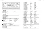
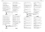
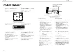
1. Connect the headphones into PHONES jack.

Connect the monitor speaker into OUTPUT jack.
(It has no problem to check the signal with an 
oscilloscope.)
Raise [EXPANSION VOLUME] suitably.

2. Check that no sound is heard from the headphones and 

the monitor speaker.

3. Press [F5(TEST)],then check that a sine wave sound is 

heard from left channels.

4. Press [F5(TEST)] again,then check that a sine wave sound 

is heard from right channels.

5. Press [F5(TEST)] once more,then check that a sine wave 

sound is heard from both channels.

6. Press [F5(TEST)] once more,then check that no sound is 

heard from both channels.

7. After checking,disconnect the headphones and the monitor 

speaker.
Press [F6(NEXT)] to advance to TEST 9: CLICK.

*  If the sound is NOT heard correctly, check the following.

VE-GSPro

IC101,IC102,IC103,IC130 and circumference chips on the 
JACK BOARD

VR BOARD and wiring connecting it

fuji-card connecting MAIN BOARD and JACK BOARD

1.

ヘッドホンを

PHONES

ジャックに接続します。

モニタースピーカーを

OUTPUT

ジャックに接続します。

(

出力波形をオシロスコープで確認しても構いません。)

[EXPANSION VOLUME]

を適当に上げます。

2.

ヘッドホンとモニタースピーカーからは音が出力されてい

ないか確認します。

3. [F5(TEST)]

を押し、左側からサイン波の音がするか確認し

ます。

4.

再び

[F5(TEST)]

を押し、右側からサイン波の音がするか

確認します。

5.

再び

[F5(TEST)]

を押し、両側からサイン波の音がするか

確認します。

6.

再び

[F5(TEST)]

を押し、両側とも音が出力されていない

か確認します。

7.

確認が終わったら、ヘッドホンとモニタースピーカーの

ケーブルを外し、

[F6(NEXT)]

を押します。

※ 発音に異常がある場合、以下をチェックしてください。

 VE-GSPro

 JACK 

BOARD

IC101,IC102,IC103,IC130

および周辺回

 VR 

BOARD

およびワイヤリング

 MAIN 

BOARD

JACK BOARD

を結ぶフジカード

TEST 9: CLICK

TEST 9: CLICK

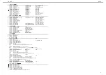
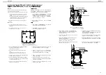
1. A metronomic click will sound from internal speaker.

2. Check the volume change by turning [CLICK LEVEL] on 

the rear panel.

3. Connect the headphones into PHONES jack, then check 

that the sound is only heard from the headphones which 
overrides internal speaker.

4. After checking,disconnect the headphones.

Press [F6(NEXT)] to advance to TEST 10: RESULT.

*  If no sound is heard, check the following.

SP101,JK102,VR101 and circumference chips on the 
JACK BOARD

fuji-card connecting MAIN BOARD and JACK BOARD

1.

本体からクリック音が鳴り始めます。

2.

リアパネルにある

[CLICK LEVEL]

を回して、クリック音

がレベル変化するか確認します。

3.

ヘッドホンを

PHONES

ジャックに接続すると、本体から

クリック音が消え、ヘッドホンからのみクリック音がする

か確認します。

4.

確認が終わったら、ヘッドホンを外し、

[F6(NEXT)]

を押

します。

※ 発音しない場合、以下をチェックしてください。

 JACK 

BOARD

SP101,JK102,VR101

および周辺回路

 MAIN 

BOARD

JACK BOARD

を結ぶフジカード

TEST10: RESULT

TEST10: RESULT

1. When "ERR!" appears on display, the unpassed test items 

that highlighted will appear on display and the 
corresponding [TRACK] LEDs will blink.

2. The MC-80 power can be turned off in this state.

Press the corresponding blinking LED when going back to 
the unpassed test item.

1. "ERR!"

が、ディスプレイに表示されている場合、

"OK"

ならなかったテスト項目が反転表示され、対応する

TRACK

ボタンの

LED

が点滅します。

2.

この状態で電源を落とせます。

もし、

"OK"

にならなかったテスト項目に戻る場合は、対

応する点滅中の

LED

を押してください。

1. When "COMPLETED!" appears on display, it means all the 

test items have been completed.

2. The MC-80 power can be turned off in this state.

1. "COMPLETED!"

が、ディスプレイに表示されている場合、

全てのテスト項目を正常に終えたことを示します。

2.

この状態で電源を落とせます。

Summary of Contents for Micro Composer MC-80

Page 1: ...created in a song 16 MIDI 1 6 16 MIDI 1 1 1 1 100 Song Data Internal Memory Songs 1 Note Capacities approx 120 000 notes Song Length 9 998 measures 1 120 000 9 9 9 8 Storage Media 3 5 inch Micro Flop...

Page 2: ...358 303 88 mm Weight 3 3 kg 7 lbs 5 oz 3 3 kg Accessories MC 80 Owner s Manual English 71231123 Japanese 71121945 Demo Song Floppy Disk 01564556 Power Supply Cord 120V 00894378 230V 00894389 230VE 00...

Page 3: ...3 Feb 1999 MC 80 LOCATION OF CONTROLS...

Page 4: ...346045 FUJI CARD 35pin 35X110 A6 0BB P1 25 HBL10 40340045 CUSHION NW1030 1 6X60X40M 01782678 FERRITE CORE SSC 58 12 01780790 FUJI CARD 26pin 26X160 A6 0BB P1 25 HBL10 01459123 WIRING FDD POWER 0167309...

Page 5: ...C 1 40011101 Binding Taptight B 3x8mm BZC 28 40011278 Binding Taptight P 3x8mm ZC 38 40011312 Binding Taptight P 3x8mm BZC 5 40238501 Binding Taptight P 4x8mm BZC 6 40340812 Sems 3x10mm BZC 4 40011501...

Page 6: ...C 1 40011101 Binding Taptight B 3x8mm BZC 28 40011278 Binding Taptight P 3x8mm ZC 38 40011312 Binding Taptight P 3x8mm BZC 5 40238501 Binding Taptight P 4x8mm BZC 6 40340812 Sems 3x10mm BZC 4 40011501...

Page 7: ...eb 1999 MC 80 WIRING DIAGRAM fig 1 fig 1 This arrangement of wirings apply to S N ZL50100 ZL50199 fig 1 ZL50100 ZL50199 fig 2 fig 2 This arrangement of wirings apply to S N ZL70200 or later fig 2 ZL70...

Page 8: ...108 on JB 15289709 M51954BFP 600D IC RESET IC105 on JB TRANSISTOR 15129164 DTC114ESTP DIGITAL TORANSISTOR Q501 508 on PB 15309101 2SA1037K T146 QRS TRANSISTOR CHIP Q103 105 110 on JB 15309103 2SA1202Y...

Page 9: ...011312 SCREW M3X8 BINDING P TITE FE BZC 40011501 SCREW M3X8 SEMS PAN HEAD FE BZC 40011889 EXTERNAL TOOTH WASHER M4 FECM 40012301 SCREW M4X8 BIND TAPTITE B FE ZC 40013067 SCREW M3X8 PAN SEMS FE ZC 4023...

Page 10: ...de Disk Read WIRING FDD WIRING FDD POWER MC 80 JACK BOARD Required item MIDI cable 2HD and 2DD Floppy Disk Formatted Headphones RH 120 etc Monitor Speaker MA 12 etc 2 Foot Switches FS 5U etc and PCS 3...

Page 11: ...r DRAM is defective Check IC3 IC5 IC2 on the MAIN BOARD CPU ROM PROGRAM ROM D RAM MAIN BOARD IC3 IC5 IC2 Install ZIP INT 1A or HDP 88 in the MC 80 ZIP INT 1A HDP 88 MC 80 Insert a formatted ZIP disk i...

Page 12: ...NCODER TEST6 LCD ENCODER 1 Press ENTER to test appears on display 2 Press ENTER then check that all dots of display are turned off 3 Press ENTER again then check that all dots of display are turned on...

Page 13: ...T 4 F5 TEST 5 F5 TEST 6 F5 TEST 7 F6 NEXT VE GSPro JACK BOARD IC101 IC102 IC103 IC130 VR BOARD MAIN BOARD JACK BOARD TEST 9 CLICK TEST 9 CLICK 1 A metronomic click will sound from internal speaker 2 C...

Page 14: ...8 2 8 BLOCK DIAGRAM MIDI IN 1 MIDI IN 2 MIDI THRU MIDI OUT 1 MIDI OUT 2 FOOT SW CPU SH7021 DRAM 16Mbit IC3 IC2 FLASH ROM 8Mbit GATE ARRAY M60205 0601FP ENCODER SW LED PANEL SWITCH BOARD IC5 IC4 LCDC S...

Page 15: ...5 6 6 6 6 7 7 7 7 8 8 8 8 9 9 9 9 1 0 1 0 1 0 1 0 1 1 1 1 1 1 1 1 1 2 1 2 1 2 1 2 1 3 1 3 1 3 1 3 1 4 1 4 1 4 1 4 1 5 1 5 1 5 1 5 1 6 1 6 1 6 1 6 1 7 1 7 1 7 1 7 1 8 1 8 1 8 1 8 1 9 1 9 1 9 1 9 2 0 2...

Page 16: ...2 2 2 2 3 3 3 3 4 4 4 4 5 5 5 5 6 6 6 6 7 7 7 7 8 8 8 8 9 9 9 9 1 0 1 0 1 0 1 0 1 1 1 1 1 1 1 1 1 2 1 2 1 2 1 2 1 3 1 3 1 3 1 3 1 4 1 4 1 4 1 4 1 5 1 5 1 5 1 5 1 6 1 6 1 6 1 6 1 7 1 7 1 7 1 7 1 8 1 8...

Page 17: ...3 3 4 4 4 4 5 5 5 5 6 6 6 6 7 7 7 7 8 8 8 8 9 9 9 9 1 0 1 0 1 0 1 0 1 1 1 1 1 1 1 1 1 2 1 2 1 2 1 2 1 3 1 3 1 3 1 3 1 4 1 4 1 4 1 4 1 5 1 5 1 5 1 5 1 6 1 6 1 6 1 6 1 7 1 7 1 7 1 7 1 8 1 8 1 8 1 8 1 9...

Page 18: ...3 3 3 4 4 4 4 5 5 5 5 6 6 6 6 7 7 7 7 8 8 8 8 9 9 9 9 1 0 1 0 1 0 1 0 1 1 1 1 1 1 1 1 1 2 1 2 1 2 1 2 1 3 1 3 1 3 1 3 1 4 1 4 1 4 1 4 1 5 1 5 1 5 1 5 1 6 1 6 1 6 1 6 1 7 1 7 1 7 1 7 1 8 1 8 1 8 1 8 1...

Page 19: ...10 RA2 10k 1 2 3 4 5 6 7 8 9 10 RA1 10k 1 2 3 4 5 6 7 8 9 10 RA3 10k 1 2 3 4 5 6 7 8 9 10 RA4 10k 1 2 3 4 5 6 7 8 9 10 C37 0 1 IC9C TC7W02F 8 4 C30 0 1 C31 0 1 CN3 52045 3545 1 1 2 2 3 3 4 4 5 5 6 6...

Page 20: ...k C130 47P R169 100k R172 1k R170 100k R173 1k C157 0 01 C158 0 01 DA101 DCG010 TL 1 2 3 DA102 DCF010 TL 1 2 3 R154 10k R171 4 7k C159 100P IC106F HD74LS05FP 13 12 R164 4 7k R157 10k C152 0 1 R158 10k...

Page 21: ...00 1 8 2 7 3 6 4 5 RA111 100 1 8 2 7 3 6 4 5 RA121 100 1 8 2 7 3 6 4 5 IC117B TC7W04F 3 5 IC117A TC7W04F 1 7 RA115 1k 1 8 2 7 3 6 4 5 RA110 10k 1 2 3 4 5 6 7 8 9 10 RA112 10k 1 2 3 4 5 6 7 8 9 10 C212...

Page 22: ...28 1 2 SW532 1 2 SW538 1 2 SW544 1 2 SW509 1 2 SW531 1 2 SW508 1 2 SW521 1 2 SW507 1 2 SW515 1 2 SW530 1 2 SW529 1 2 SW541 1 2 SW533 1 2 Q501 DTC114ES 3 1 2 C502 0 1 C501 0 1 Q502 DTC114ES 3 1 2 Q503...

Page 23: ...202K 1 2 3 DA308 DAN202K 1 2 3 DA306 DAN202K 1 2 3 DA307 DAN202K 1 2 3 DA311 DAN202K1 2 3 DA310 DAN202K1 2 3 DA309 DAN202K1 2 3 DA301 DAN202K 1 2 3 DA302 DAN202K 1 2 3 DA303 DAN202K 1 2 3 SW314 1 2 4...

Page 24: ...all the supplied core and fuji card CN108 8 Re attach the bottom cover 9 Checking operation a Prepare an external ZIP drive a 25pin SCSI cable and a formatted ZIP disk b Connect the external ZIP drive...

Page 25: ...onnecting the MC 80 IDE BOARD and the ANGLE HD L R See fig 4 d 6 Remove the WIRING IDE and the WIRING IDE POWER from the MC 80 IDE BOARD s connectors CN401 CN402 on the DD HOLDER See fig 4 e 7 Remove...

Page 26: ...take them back from customer As follows re install the parts listed above in the MC 80 before installing the internal hard disk drive unit a Turn off the power for the MC 80 and any connected devices...

Page 27: ...alize the hard disk Connect the AC Cord and turn on the MC 80 power a Press TOOLS b Press F5 DISKUTIL c Press F6 MENU to select DISK MENU d Press F4 FORMAT e Press F1 DRIVE several times to select the...

Reviews: