25
Feb,1999
MC-80
INSTALLING THE INTERNAL ZIP DRIVE UNIT(ZIP-INT-1A)
/
/
/
/
内蔵
内蔵
内蔵
内蔵
ZIP
ドライブユニット(
ドライブユニット(
ドライブユニット(
ドライブユニット(
ZIP-INT-1A
)の取り付け方法
)の取り付け方法
)の取り付け方法
)の取り付け方法
♦
♦
♦
♦
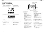
NOTICE:
When the internal hard disk drive unit(HDP-88) has already
been installed in customer’s MC-80,
Remove it before installing the internal ZIP drive unit as follows.
a. Turn off the power for the MC-80 and any connected
devices, and disconnect any cables connected to the
MC-80.
b. Seeing page "INSTALLING THE INTERNAL HARD DISK
DRIVE UNIT(HDP88)", remove the internal hard disk
drive unit from step8 to step2 in reverse steps.
* Return the internal hard disk drive unit with the MC-80 to
customer.
♦
♦
♦
♦
Procedure:
1. Turn off the power of the MC-80 and the connected
devices, and disconnect all cables that are connected to
the MC-80.
2. Turn the MC-80 over, and remove the bottom cover.
(See fig.1 to remove 12 screws.)
◆お読みください
◆お読みください
◆お読みください
◆お読みください
お客さまの
MC-80
に内蔵ハードディスク
(HDP88)
が取り付け
られている場合、内蔵
ZIP
ドライブユニットを取り付ける前に
以下の手順で内蔵ハードディスクを外しておきます。
a. MC-80
と接続している機器の電源を切り、
MC-80
に接続
されているすべてのケーブルを外します。
b.
「内蔵ハードディスクドライブユニット(
HDP88
)の取
り付け方法」を参照し、手順
8
から
2
へ、逆の手順で内
蔵ハードディスクを外してください。
※ 取り外した内蔵ハードディスクは、
MC-80
とともにお客様
に返却してください。
◆手順
◆手順
◆手順
◆手順
1. MC-80
と接続している機器の電源を切り、
MC-80
に接続
されているすべてのケーブルを外します。
2. MC-80
を裏返し、ボトムカバーを外します。
(外すネジは
fig.1
を参照してください。)
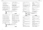
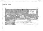
fig.1 Bottom Cover View
Remove 12 screws circling in this figure./
fig.1 Bottom Cover View
Remove 12 screws circling in this figure./
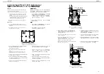
3. Remove the WIRING IDE and the WIRING IDE-POWER
from the MC-80 JACK BOARD’s connectors
(CN111,CN103). (See fig.4-(a))
4. After taking off a shield sheet from the DD HOLDER
gently,
(See fig.4-(b)) remove 4 screws connecting the DD
HOLDER and the boss of a top case.(See fig.4-(c))
5. Remove 2 screws connecting the MC-80 IDE BOARD and
the ANGLE HD L/R.(See fig.4-(d))
6. Remove the WIRING IDE and the WIRING IDE-POWER
from the MC-80 IDE BOARD’s connectors(CN401,CN402)
on the DD HOLDER.(See fig.4-(e))
7. Remove 4 screws connecting the DD HOLDER and the
ANGLE HD L/R.(See fig.4-(f))
3. WIRING IDE
と
WIRING IDE-POWER
をジャックボードの
CN111,CN103
から取り外します。(
fig.4-(a)
参照)
4. DD
ホルダーに付いているシールドシートを丁寧にはがし
た後、(
fig.4-(b)
参照)
DD
ホルダーとトップケースのボス
を止めているネジ4本を外します。(
fig.4-(c)
参照)
5. IDE
ボードとアングル
HD-L/R
を止めているネジ2本を外
します。(
fig.4-(d)
参照)
6.
取り外した
DD
ホルダーに付いている
IDE
ボード上の
WIRING IDE
と
WIRING IDE-POWER
を
CN401,CN402
か
ら外します。(
fig.4-(e)
参照)
7. DD
ホルダーとアングル
HD-L/R
を止めているネジ4本を
外します。(
fig.4-(f)
参照)
CN107
CN110
CN108
CN111
CN103
CN105
CN106
MC-80 JACK BOARD
WIRING IDE
WIRING
IDE-POWER
DD HOLDER
ANGLE HD-R
ANGLE HD-L
MC-80 IDE BOARD
CN402
CN403
(a)
(a)
(c)
(c)
(c)
(c)
CN401
(d)
(d)
(e)
(e)
(b)
(f)
(f)
(f)
(f)
fig4. before installing the ZIP-INT-1A
8. After securing the ZIP drive to the DD HOLDER with 4
screws, (See fig.5-(g)) connect the WIRING IDE and the
WIRING IDE-POWER to the ZIP drive’s connector
properly.(See fig.5-(h))
9. Secure this DD HOLDER to the boss of a top case with 4
screws. (See fig.5-(i))
10.Connect the WIRING IDE-POWER to the MC-80 JACK
BOARD’s connector(CN103).
And connect the WIRING IDE to the MC-80 JACK
BOARD’s connector(CN111).(See fig.5-(j))
11.After re-sticking a shield sheet to the DD HOLDER, attach
the bottom cover. (See fig.5-(k))
8. DD
ホルダーと
ZIP
ドライブを先ほど外したネジ4本で止
めます。(
fig.5-(g)
参照)
ZIP
ドライブのコネクタに
WIRING IDE
と
WIRING IDE-
POWER
を挿します。(
fig.5-(h)
参照)
9. ZIP
ドライブの付いた
DD
ホルダーをトップケースのボス
に合わせて、ネジ4本で止めます。(
fig.5-(i)
参照)
10.WIRING IDE-POWER
をジャックボードの
CN103
に挿し
た後、
WIRING IDE
を
CN111
に挿します。(
fig.5-(j)
参照)
11.
元のようにシールドシートを
DD HOLDER
に貼り付けた
後、ボトムカバーを取り付けます。(
fig.5-(k)
参照)
CN107
CN110
CN108
CN111
CN103
CN105
CN106
MC-80 JACK BOARD
WIRING
IDE-POWER
DD HOLDER
(i)
(i)
(i)
(i)
(h)
(g)
(g)
(g)
(g)
(k)
WIRING
IDE
(h)
(j)
(j)
ZIP-INT-1A
fig5. after
installing
the
ZIP-INT-1A


