background image

o

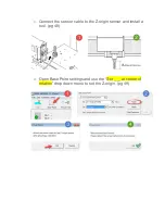
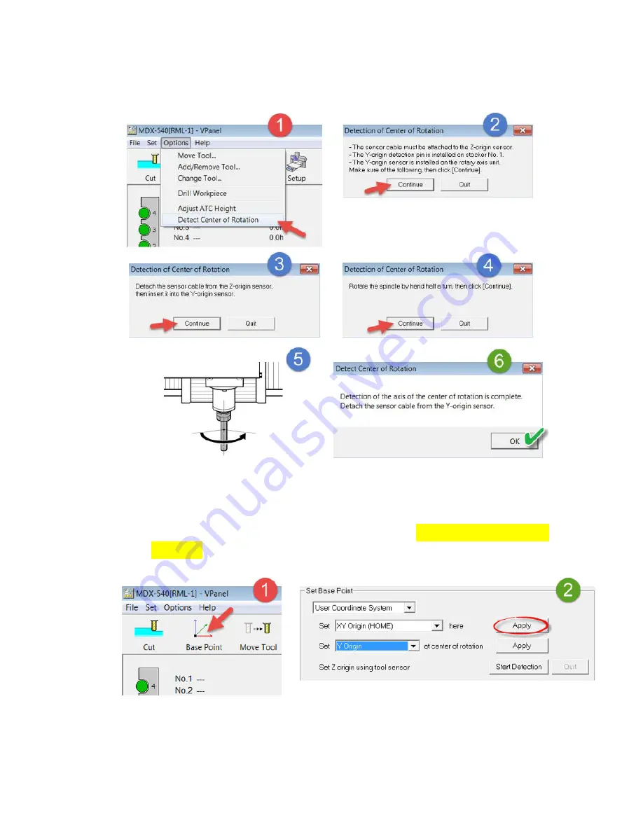
  Begin the “Detect Center of Rotation” process. (pg 45-46) 


  Set your Y and Z origins at the center of the A axis. (pg 47-49) 


o

  Open Base Point settings and use the “Set ___ at center of 

rotation” drop down menu to set the Y-origin. (pg 47) 


Summary of Contents for MODELA PRO II series

Page 1: ...and MDX 540 fine tune the accuracy of their machine when using the 4th axis option ZCL 540 The following steps will assist users who observe any shifts or offsets when performing double sided milling We will cover two sections Section 1 Setting Origins Section 2 Manual Adjustments ...

Page 2: ...ection 1 Make sure to have your ZCL 540 user manual handy Begin the Y origin sensor detection process pg 43 46 o Connect the sensor cable to the Z origin sensor pg 43 o Install Y origin sensor bar pg 44 ...

Page 3: ...Detect Center of Rotation process pg 45 46 Set your Y and Z origins at the center of the A axis pg 47 49 o Open Base Point settings and use the Set ___ at center of rotation drop down menu to set the Y origin pg 47 ...

Page 4: ...o Connect the sensor cable to the Z origin sensor and install a tool pg 48 o Open Base Point settings and use the Set ___ at center of rotation drop down menu to set the Z origin pg 49 ...

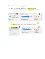
Page 5: ...o Move your tool to the right of your work piece along the X axis and set your X origin using the Set ___ here drop down menu pg 50 o Move you re Axis to a zero degree position and use the Set ___ here drop down menu to set the A origin pg 51 ...

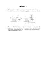
Page 6: ...e seam of the part to find any adjustment values pg 53 Observe what direction this shift occurs to determine what type of adjustment value you will use For example if the top of the part looks like it shifted upwards the Y direction then your adjustment value will be negative pg 53 ...

Page 7: ...e Point in VPanel to correct your Y origin position For example if you had a measured adjustment value of 2mm then you would change the location of your Y origin by 1mm only pg 53 Check your part in the Z direction for any similar adjustment values pg 53 ...

Page 8: ...ur adjustment will be 1mm pg 53 Re cut your part under these new origin settings to double check that your adjustments were correct If you continue to have issues return to Section 2 and repeat the calibration process You can also visit our product support page to download a 20mm cubic test file ZCL 540_Calibration_Cube to help with this process ...

Reviews: