15
MC-09
*
Holding down [SETUP] and [TAP] proceeds to the next item.
3: MIDI Test
Confirm open and short statuses of MIDI IN and OUT.
Connect 1 MIDI cable to MIDI IN/OUT connector to form a loop beforehand.
“000” indicating short status is displayed.
Remove the MIDI cable connection.
*
If the MIDI cable is not connected beforehand, “---” indicating open status is
displayed.In this case, connect 1 MIDI cable to MIDI IN/OUT connector to form
a loop.When confirmed to be O.K., it will automatically proceed to the next item.
4: SW/ LED Test
Checking the LED and SW operations.
Initially, all LEDs corresponding to all the switches will light. Confirm that all
LEDs are lit. Pressing each SW turns off the corresponding LED.
If the SW has an LED, the LED will go out. For SWs without LEDs, the LEDs
will correspond to the SWs as shown in the chart below.
*
There is no reaction when 2 or more SWs are held down. Pressing all SWs and
turning off all LEDs will automatically proceed to the next item.
5: VR test
Confirm whether or not the volume functions properly.
Initially, “Vr” appears on the display.Rotating each volume control will
display volume value “000”-”127” for whichever one is currently being
operated.
All LEDs will blink when minimum “000” and maximum “127” values for each
volume are properly obtained.
Completing all volume checks will automatically proceed to the next item.
*
Output volume is not included in this test.
6: BYPASS Test
Checks for residual noise and whether or not the signal input from INPUT is
properly output from OUTPUT. “BPS” appears on the display.
6-1: Confirmation of Residual Noise Rotate the OUTPUT volume control to its
maximum position.
Check the residual noise of the output signal from the rear OUTPUT jack with
the noise meter.
The residual noise level is as follows.
•
75 dBm or lower (JIS-A)
6-2:Confirming Output Signal Input oscillator
signal to the rear INPUT jack.
Input signal: 100Hz/ 1kHz/ 10kHz: +6dBm sinewave
Rotate the OUTPUT volume control to its maximum position.
Measure the level of the output signal from the rear OUTPUT jack with the
noise meter.
Confirm that the output signal level for each input signal is within the range of
+4dBm - +8dBm.
For 1kHz sinewaves only, check for distortions in wave form with the
oscilloscope.
*
Holding down [SETUP] and [TAP] proceeds to the next item.
7: Initialize
Reset the user memory built into the main unit to factory shipment setting.
After “ini” appears for a few seconds on the display, “Sur” appears and blinks.
Press the [Enter] button to execute.
“BSY” appears on the display during execution.
Requires approximately one minute to complete.
“ini” reappears on the display when initialization is completed.
*
”End” appears on the display when [SETUP] and [TAP] are held down and
switching to normal mode is done automatically.
Error number and error content
ER1
Checksum error in Flash ROM.
ER2
Access error in Work RAM.
ER3
Access error in EEP ROM.
ER4
Access error in ESP RAM.
ER5
Access error in Smart Media.
SWs without LEDs
Corresponding to LEDs
[DISPLAY] button
[BPM]
[INC] button
[OCT]
[DEC] button
[TONE/TYPE]
[TAP] button
“8” of right part of 7-segment dis-
play
[SHIFT] button
“8” of left part of 7-segment display
[ENTER] button
[FROM]
[EXIT] button
[TO]
[STOP] button
Beat LED (located close to the Mem-
ory Card connector)
Summary of Contents for Phase Lab MC-09
Page 3: ...3 MC 09...
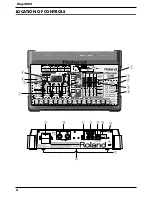
Page 4: ...4 May 2002 LOCATION OF CONTROLS fig top...
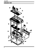
Page 6: ...6 May 2002 EXPLODED VIEW fig explo 1 8 2 9 4 5 6 10 7 a b b c c c c c b 3...
Page 11: ...11 MC 09...
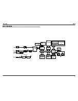
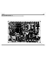
Page 17: ...19 May 2002 MC 09 CIRCUIT BOARD MAIN BOARD 1 2 fig block View from component side...
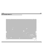
Page 18: ...21 May 2002 MC 09 CIRCUIT BOARD MAIN BOARD 2 2 fig block View from foil side...


