background image

26

Setting the scanning area

If you wish to limit the scanning area, such as in cases where you wish to scan only a portion of an object, make the settings as described
below.

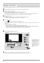
Click [Scanning Area] in the Controller window.  The [Scanning Area] dialog box appears.

1

Make the settings for the scanning area.
Make the settings to match the location where the scan object is secured in place.
Either of the following two methods can be used to make the settings.
- Use the mouse to move the blue frame on screen.

- Enter the numerical values for the upper-right and lower-left points.

The size of the on-screen scanning area (shown in blue) changes to match the values that are entered.

2

5

Click [Begin Area Test].
The sensor moves to a position above an outer point on the scanning area that has been set.
Make sure the scan object that has been secured in place lies within the area.

3

Click [Z Upper Limit].

The cursor 

 is displayed on the Z upper-limit setting on screen.

Specify the highest position of the scan object.  Clicking [Apply] or double-clicking on the target lowers the sensors to the target's
center position.
If the target is displaced, redo the settings.

   * Set the Z upper limit to the highest position on the object to be scanned.

During scanning, if the sensor detects a position higher than the Z upper-limit setting, the setting is cleared and
scanning continues with the greatest scan height of Dr. PICZA as the Z upper limit.

4

4

3

2

4

After determining the scanning area, click [OK].

5

4

• For the scanning area and Z

upper limit, please refer to
"About scanning conditions
and the scanning area".

• For details about the buttons

on the scanning-region
setting screen, please refer to
the help screens for Dr.
PICZA.

6

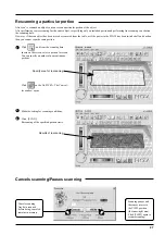
Check the scanning conditions in the Controller window one more time, then click  [SCAN] .
Scanning starts.  (During scanning, the sensor may emit a transmission sound, but this is normal.)

Summary of Contents for Picza PIX-30

Page 1: ...ely and store it in a safe location Unauthorized copying or transferral in whole or in part of this manual is prohibited The contents of this operation manual and the specifications of this product are subject to change without notice The operation manual and the product have been prepared and tested as much as possible If you find any misprint or error please inform us USER S MANUAL ...

Page 2: ...ful interference in which case the user will be required to correct the interference at his own expense Unauthorized changes or modification to this system can void the users authority to operate this equipment The I O cables between this equipment and the computing device must be shielded For Canada CLASS A NOTICE This Class A digital apparatus meets all requirements of the Canadian Interference ...

Page 3: ...are 8 Adding 3D graphics to an internet web page 9 Cutting a three dimensional object with a modeling machine 10 1 Check the included items 11 2 Part names 11 3 Setting up and connection 12 4 Installing the Dr PICZA 14 Symbols used in the section on software 14 Overview of Dr PICZA 14 Installing 15 5 Starting Dr PICZA 17 About Help 17 6 Selecting a communication port 18 7 Powering ON 19 8 Load the...

Page 4: ...e done is indicated by the design contained within the circle The symbol at left means the power cord plug must be unplugged from the outlet Do not disassemble repair or modify Doing so may lead to fire or abnormal operation resulting in injury Do not use with any electrical power supply that does not meet the ratings displayed on the AC adapter Use with any other power supply may lead to fire or ...

Page 5: ... cord leading to electrocution or fire Do not allow liquids metal objects or flammables inside the machine Such materials can cause fire Do not allow children to operate without adult supervision or operate within reach of young children Doing so may result in injury When unplugging the AC adapter from the power outlet grasp the adapter unit or the plug not the cord Unplugging by pulling the cord ...

Page 6: ...oduct and the AC adapter The following figure describes the location The configuration of the AC adapter varies according to regional differences in voltage Please note that the descriptions in this manual are for the 117 V adapter Do not place hands near the main unit while in operation Rating label Do not use with any electrical power supply that does not meet the ratings displayed on the AC ada...

Page 7: ...r ce qu il doit faire La chose spécifique à faire est indiquée par le dessin à l intérieur du cercle Le symbole à gauche signifie que le fil électrique doit être débranché de la prise Pour utiliser en toute sécurité Ne pas démonter réparer ou modifier Le non respect de cette consigne pourrait causer un incendie ou provoquer des opérations anormales entraînant des blessures Ne pas utiliser avec une...

Page 8: ... l adaptateur AC saisir et tirer le bloc adaptateur et non le fil électrique Débrancher en tirant sur le fil pourrait l endommager et risquer de provoquer un incendie ou une électrocution Ne pas débrancher l adaptateur AC avec des mains mouillées Une négligence à ce niveau pourrait provoquer des décharges électriques Ne pas introduire de liquide d objet métallique ou inflammable dans l appareil Ce...

Page 9: ...oltage régionales Veuillez noter que les descriptions dans ce manuel correspondent à un adaptateur de 117 volts Étiquette des caractéristiques électriques Ne pas utiliser avec une alimentation électrique ne respectant pas les caractéristiques indiquées sur l adaptateur Quand l appareil reste inutilisé pendant une longue période débrancher l adaptateur AC Ne pas placer vos mains près de l unité pri...

Page 10: ... 3D computer graphics software which must be obtained from another source Visualize in detail the design illustration you wish to create In this example we ll make the illustration shown below 2 Create the elements that make up the illustration In this example we ll use the clay included with the product to make the face and the graphics software to make the other element the pyramid 3 Scan the cl...

Page 11: ... 1 Set the lure in place on the workpiece table and scan it with the PIX 30 In this example we ll scan only one side of the lure and use Dr PICZA s Add Backside Faces function to make a complete three dimensional representation 2 Use Dr PICZA to color the scanned data For details on adding color please refer to the help screens for Dr PICZA 3 Under File Preferences click Add Backside Faces to turn...

Page 12: ...ersion After inversion Export to MODELA PLAYER Cutting a three dimensional object with a modeling machine Dr PICZA has a function for exporting data to MODELA PLAYER MODELA PLAYER is software for cutting three dimensional objects on the MODELA CAMM 3 or CAMM 2 three dimensional modeling machines made by Roland DG Corp Dr PICZA can output 3D data directly to MODELA PLAYER In this example we ll use ...

Page 13: ... inside the cover except during scanning Table The grid on the table serves as a guide for mounting the object to scan It does not indicate the scanning area for Dr PICZA The scale is in 10 mm about 3 8 in units STANDBY LED Do not put hands inside AC adapter jack Serial connector Roland Software Package CD ROM 1 The configuration of the AC adapter varies according to regional differences in voltag...

Page 14: ...104 F and within a humidity range of 35 to 80 Securely connect the power cord computer I O cable and so on so that they will not be unplugged and cause failure during operation Doing so may lead to faulty operation or breakdown NOTICE When you carry the PIX 30 use two hands to securely grip this area on the left and right sides Never install this unit in any of the following situations as it could...

Page 15: ...ward If the mounted scan object the three dimensional object to be scanned is larger than the table size it may extend beyond the front and rear of the unit Do not place any objects in the area For the cable use a commercially available crossover serial cable RS 232C rating A straight serial cable such as is commonly used to connect a modem cannot be used For more on how to connect a serial cable ...

Page 16: ...change Overview of Dr PICZA A Quick Overview of Available Functions Toolbar button View scanned 3D data from various angles Zoom in or out on the on screen view of scanned data Make settings for how scanned 3D data is displayed Color the faces of scanned 3D data Adjust the slant of scanned 3D data Specify the data format and save the scanned 3D data Launch the MODELA PLAYER Set scanning conditions...

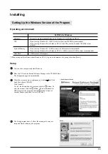
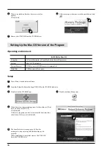
Page 17: ...onment Computer CPU System Memory Hard Disk Switch on the computer and start Windows 1 2 Place the CD from the Roland Software Package in the CD ROM drive The Setup menu appears automatically When the screen shown at right appears click the in Click here then choose PIX 30 Click Install To view the description of a program click the button To view the manual click the button There are manuals in P...

Page 18: ... 6 Remove the CD ROM from the CD ROM drive 7 The Installer s start screen appears Follow the messages to carry out setup and finish setting up the program When installation is completed remove the CD ROM from the CD ROM drive 6 Setup Double click the CD ROM icon 3 Double click the Menu icon 4 Turn off any virus detection software 1 2 Insert the Roland Software Package CD ROM in the CD ROM disk dri...

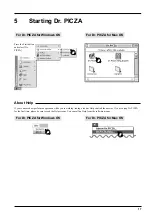
Page 19: ...look at Help can find the answer If you re using Dr PICZA for the first time please be sure to read the Help screens You can call up Help from the software menus For Dr PICZA for Windows OS Press the Start button and select Dr PICZA For Dr PICZA for Mac OS For Dr PICZA for Windows OS For Dr PICZA for Mac OS ...

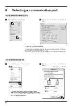
Page 20: ...e change the setting of Dr PICZA so as to use another port Or disable the AppleTalk 6 Selecting a communication port From the File menu click Settings 1 Select the port where the cable is connected then click OK 2 For Dr PICZA for Windows OS If You re Using Windows NT 4 0 If the printer port for Windows driver and the communication port for Dr PICZA are set to the same port you cannot use Dr PICZA...

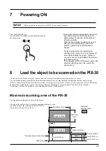
Page 21: ...r Dr PICZA The scale is in 10 mm 3 8 in units 304 8 mm 12 in Maximum scanning area 203 2 mm 8 in 60 5 mm 2 3 8 in 10 mm 3 8 in 30 mm 1 3 16 in 30 mm 1 3 16 in 70 mm 2 6 8 in Upper surface Front surface Spacer Spacer Table surface This space cannot be scanned 7 Powering ON Before switching on the power to the PIX 30 turn on the computer NOTICE Press the STANDBY key The STANDBY LED lights up and ori...

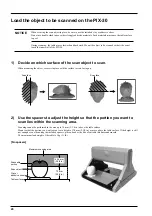
Page 22: ...b Maximum scanning area No spacers 60 5 mm 2 3 8 in Table surface Clay or adhesive sheet Scan object Scannable portion 70 mm 2 3 4 in 1 Decide on which surface of the scan object to scan When mounting the object secure it in place with the surface to scan facing up Load the object to be scanned on the PIX 30 When securing the scan object in place be sure to use the included clay or adhesive sheet ...

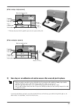
Page 23: ...aking it impossible to hold a scan object in place A scan object which does not topple over when placed with the scan surface facing up is suited to being held in place by the adhesive sheet For other shapes use clay to secure in place When using two spacers When using a single spacer Maximum scanning area If the scan object protrudes beyond the spacer use two spacers side by side Spacer Maximum s...

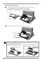
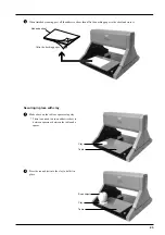
Page 24: ...ure it in place 2 Adhesive sheet Scan object Table Securing in place with adhesive sheet Peel off the backing paper from both sides of the adhesive sheet and affix the sheet to the table or a spacer Do not discard the backing paper It is needed for storing the adhesive sheet after use If necessary you can also cut the sheet to match the size of the scan object and spacers There is no need to use a...

Page 25: ... an adhesive sheet to between spacers or between the table and a spacer 1 Press the scan object into the clay to hold it in place 2 Table Clay Scan object Table When finished scanning peel off the adhesive sheet then affix the backing paper to the sheet and store it 3 Adhesive sheet Affix the backing paper ...

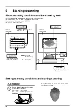
Page 26: ... in operation Doing so may result in injury Doing so may lead to faulty operation or breakdown Setting scanning conditions and starting scanning Y SCAN PITCH Spacing of adjacent scan points along the Y axis Scanning Area Scan path Draft scanning Scan points Scanning area Maximum scanning area Maximum scanning area Z BOTTOM Height of the scanning area s bottom plane The explanations here and after ...

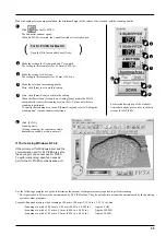
Page 27: ...arts During scanning the sensor may emit a transmission sound but this is normal 3 6 5 4 For Dr PICZA for Mac OS Open the File menu and choose New For detailed description of the available Controller buttons please refer to the help screens for Dr PICZA Use the following examples as a guide to determine the amount of computer memory required to perform scanning The figures shown below are the amou...

Page 28: ...n place lies within the area 3 Click Z Upper Limit The cursor is displayed on the Z upper limit setting on screen Specify the highest position of the scan object Clicking Apply or double clicking on the target lowers the sensors to the target s center position If the target is displaced redo the settings Set the Z upper limit to the highest position on the object to be scanned During scanning if t...

Page 29: ... 30 has been switched off and back on then you cannot scan the same portion Click and from the scanning data shown on the screen select a portion to rescan You can specify a number of noncontinuous portions 1 Click on the Dr PICZA The Control ler window opens Cancels scanning Any data scanned before being canceled remains in memory Scanning pauses and the sensor moves to the VIEW position the inne...

Page 30: ...the electrical insulation Edit the scanned data The shape of an object can be edited It is possible to vary the height adjust the slant or perform concave convex inversion height inversion for a desired surface You can use the toolbar button or select Edit on the menu bar Please refer to the help screens for Dr PICZA for detailed explanations of the various functions that are available Be sure to ...

Page 31: ...nd the cable connecting the unit to the computer secure Are the AC adapter and the cable connecting the unit to the computer free of any internal broken wires Is the operation of the computer correct Was the power to the computer switched on before the PIX 30 was turned on Be sure to power up the computer first then switch on the power to the PIX 30 Was the computer restarted When the computer has...

Page 32: ... External dimensions 478 mm W x 465 mm D x 341 mm H 18 7 8 in W x 18 5 16 in D x 13 7 16 in H Weight unit only 11 kg 24 2 lb Operation temperature 5 40 C 41 104 F Operation humidity 35 80 no condensation Accessories Roland Software Package CD ROM 1 AC adapter 1 clay 1 adhesive sheets 2 spacers 2 PIX 30 user s manual 1 Interface Specification Serial Standard RS 232C specifications Transmission meth...

Page 33: ... not individually licensed to use this Software You may use the Software by one person with using a single computer in which the Software is installed 4 Reproduction You may make one copy of the Software only for back up purpose The property of the copied Software belongs to Roland You may install the Software into the hard disk of a single computer 5 Cancellation Roland retains the right to termi...

Reviews: