9
Panel Descriptions
Rear Panel
1
4
5
2
3
1
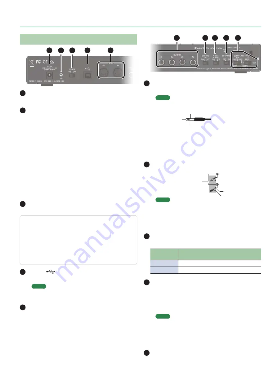
DC IN jack
Connect the included AC adaptor here.
2
Ground terminal
Depending on the circumstances of a particular setup, you may
experience a discomforting sensation, or perceive that the surface
feels gritty to the touch when you touch this device, microphones
connected to it, or the metal portions of other objects, such as
guitars. This is due to an infinitesimal electrical charge, which is
absolutely harmless. However, if you are concerned about this,
connect the ground terminal with an external ground. When
the unit is grounded, a slight hum may occur, depending on the
particulars of your installation. If you are unsure of the connection
method, contact the nearest Roland Service Center, or an
authorized Roland distributor, as listed on the
“Information”
page.
* Unsuitable places for connection
5
Water pipes (may result in shock or electrocution)
5
Gas pipes (may result in fire or explosion)
5
Telephone-line ground or lightning rod (may be dangerous in
the event of lightning)
3
[POWER] switch
Turns the power of the Rubix on/off.
Concerning the Auto Off function
This unit automatically powers-off in the following conditions
(Auto Off function).
5
The unit is not connected to a computer or tablet
5
There has been no audio input for 10 hours
If you don’t want the unit to power-off automatically, connect it
to a computer or tablet.
4
USB port (
)
Connects to the computer.
MEMO
The Rubix44 cannot be powered via its USB port (it will not
operate).
5
MIDI (OUT, IN) connectors
Connect the MIDI OUT connector to an external MIDI sound
module, etc.
Connect the MIDI IN connector to a MIDI keyboard or MIDI
controller.
6
9
10
7
8
6
OUTPUT (1L, 2R, 3L, 4R) jacks (balanced TRS type)
Output the analog audio signal.
MEMO
5
Pin assignment of OUTPUT jack
GND (SLEEVE)
HOT (TIP)
COLD (RING)
5
The wiring of this device uses
“impedance balancing.”
The
audio signal is conveyed via HOT and GND in unbalanced
form, but since COLD and GND are connected by a resistor,
the electrical circuit is balanced. This provides the same
noise-reducing effect as a balanced circuit.
7
[GROUND LIFT] switch
OUTPUT (1L, 2R, 3L, 4R)
jacks (balanced TRS
type)
NOR
LIFT
Normally, this switch should
be set to
“NOR”
(NORMAL).
If ground loop noise occurs,
switching this to
“LIFT”
might eliminate the noise.
MEMO
5
The GND (SLEEVE) of the OUTPUT (1L, 2R, 3L, 4R) jacks (TRS
balanced type) is disconnected from ground.
5
In some cases, there might be no sound if you connect a
balanced cable to an unbalanced device and set this switch
to the
“LIFT”
position. If so, set the switch to
“NOR.”
8
[PHONES SOURCE] switch
Selects the audio signal that is monitored in headphones.
Switch
position
Explanation
1/2
Monitor the output of OUTPUT (1L, 2R).
3/4
Monitor the output of OUTPUT (3L, 4R).
9
[LOOPBACK] switch
If this is turned on, the audio signal that is input to the INPUT (1L, 2R)
jacks and INPUT (3L, 4R) jacks is mixed with the audio signal played
back from the computer, and this mixed signal is then sent back
(returned) to the computer. You can use this for live broadcasting to
the internet.
MEMO
If you intend to turn the [LOOPBACK] switch on, you should
turn off your DAW software’s monitor function and the
monitoring function of Windows. Failing to do this will cause
oscillation (feedback) or doubling of the input sound.
10
[COMP/LIMIT TYPE] switch
Switches the response of the built-in compressor/limiter circuit


