30
* 1 : - ( 2
26
) — + ( 2
26
-1 )
* 2 : - ( 2
26
)
°
— + ( 2
26
-1 )
°
* 3 : 0 — + ( 2
26
-1 )
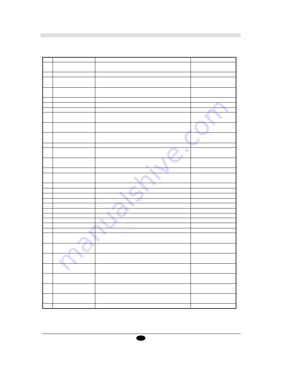
Inst.
Format
Meaning of Parameter [Parameter Range (Default)]
Explanation
CS
CS n;
n : Character set No. [0 — 4, 6 — 9, 30 — 39 (value set by cotrol panel)]
Standard Character Set
CS;
DF
DF;
None
Default
DI
DI run, rise;
run : X-axis direction vector [*1 (1)]
Absolute Direction
DI;
rise : Y-axis direction vector [*1 (0)]
DR
DR run, rise;
run : X-axis direction vector [*1 (1)]
Relative Direction
DR;
rise : Y-axis direction vector [*1 (0)]
DT
DT t;
t : Label terminator [ [ETX](CHR$(3)) ]
Define Label Terminator
EA
EA x, y;
x, y : Absolute XY coordinates of opposite angle of rectangle [*1]
Edge Rectangle Absolute
ER
ER
∆
x,
∆
y;
∆
x,
∆
y : Relative XY coordinates of opposite angle of rectangle [*1]
Edge Rectangle Relative
EW
EW r, Ø1, Øc(,Ød);
r : Radius [*1] Ø1 : Start angle [*1]
Edge Wedge
Øc : Center angle [*1] Ød : Chord tolerance [*1 (5˚)]
FT
FT n(,d(,Ø));
n : Pattern [1 — 5 (1)]
Fill Type
FT;
d : Spacing [*2 ((P2x-P1x) x 0.01)] Ø : Angle [*1 (0˚)]
IM
IM e;
e : Error mask value [0 — 255 (223)]
Input Mask
IM;
IN
IN;
None
Initialize
IP
IP P1x, P1y, P2x, P2y;
P1x, P1y : XY coordinates of P1 [*1]
Input P1 & P2
IP;
P2x, P2y : XY coordinates of P2 [*1]
IW
IW LLx, LLy, URx, URy;
x1, y1 is lower left coordinates, x2, y2 is upper right coordinates
Input Window
IW;
LB
LB c1c2c3...cn CHR$(3)
c : Character string
Label
LT
LT n(,l);
n : Pattern number [0 — 6 (solid line)]
Line Type
LT;
l : 1 pitch length [*2 (1.5% of (P2-P1))]
OA
OA;
None
Output Actual Point
OC
OC;
None
Output Commanded Position
OE
OE;
None
Output Error
OF
OF;
None
Output Facter
OH
OH;
None
Output Hard-Clip Limits
OI
OI;
None
Output Indentification
OO
OO;
None
Output Option Parameter
OP
OP;
None
Output P1 & P2
OS
OS;
None
Output Status
OW
OW;
None
Output Window
PA
PA x1, y1...,xn, yn;
xn, yn : Absolute XY coordinates [*1]
Cut Absolute
PA;
PD
PD x1, y1...,xn, yn;
xn, yn : XY coordinates [*1]
Tool Down
PD;
PR
PR
∆
1,
∆
y1...
∆
xn,
∆
yn;
∆
xn,
∆
yn : Relative XY coordinates [*1]
Cut Relative
PR;
PT
PT d;
d : Pen thickness (mm) [0—5 (0.3)]
Pen Thickeness
PT;
PU
PU x1, y1...,xn, yn;
xn, yn : XY coordinates [*1]
Tool Up
PU;
RA
RA x, y;
x, y : Absolute XY coordinates of opposite angle of rectangle [*1]
Shade Rectangle Absolute
RR
RR
∆
x,
∆
y;
∆
x,
∆
y : Relative XY coordinates of opposite angle of rectangle [*1]
Shade Rectangle Relative
SA
SA;
None
Select Alternate Set
Summary of Contents for Sign Maker CAMM-1 PNC-1050
Page 1: ...ROLAND DG CORPORATION Model PNC 1050 User s Manual SIGN MAKER...
Page 41: ...39...
Page 42: ...F2082693BE V3 1...


