3 Replacement of Main Parts
3-36
3
7
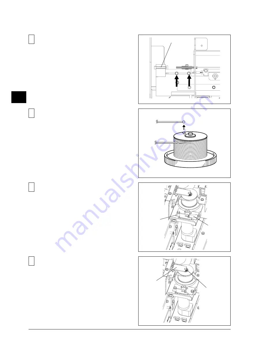
Remove the SPRING, then loosen the screws fixing the
MOTOR FLANGE.
6
Remove the CARRIAGE WIRE as shown in the figure.
8
Remove the SHAFT STAY and the E RING, then remove the
DRIVE PULLEY from the shaft.
5
Loosen the 2 screws and then the ADJUSTMENT SCREW
in order to loosen the wire tension.
ADJUSTMENT SCREW
SPRING
FLANGE
SHAFT STAY
E RING
Summary of Contents for SP-300
Page 128: ...2 Electrical Section 2 2 2 2 2 MAIN BOARD DIP SW DIP SW bit 1 bit 8 Always OFF ...
Page 134: ...2 Electrical Section 2 8 2 2 3 SERVO BOARD ...
Page 135: ...2 Electrical Section 2 9 2 ...
Page 140: ...2 Electrical Section 2 14 2 2 4 HEATER BOARD ...
Page 189: ...3 Replacement of Main Parts 3 42 3 9 Carry out the LINEAR ENCODER SETUP ...


