4-37
4 Adjustment
4
+2.0
-2.0
+1.0
-1.0
+0.5
-0.5
+0.0
-0.0
+1.5
-1.5
Scan
+2.0
-2.0
+1.0
-1.0
+0.5
-0.5
+0.0
-0.0
+1.5
-1.5
Feed
-0.5
4-9 PRINT / CUT POSITION ADJUSTMENT (Referential Time : 10min.)
[About PRINT / CUT POSITION ADJUSTMENT]
This adjustment is for calibrating the relative positions of printing and cutting.
If it is not adjusted, it could result in a problem that the cutting shifts from printing.
There are two adjusting ways prepared in this Mode, Manual and Auto.
We recommend to carry out the Manual Adjustment for more accurate adjustment.
1
Turn on the sub power switch while pressing [ ], [ ] and
[ ] keys to enter the SERVICE MODE.
Set the SV-GG media on the machine and lower the
Pinch Rollers.
2
3
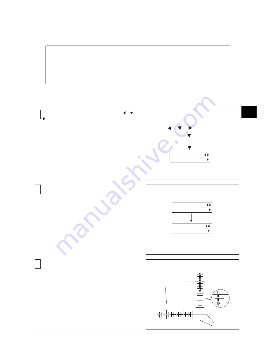
Select [TEST PRINT2] under the [PRINT&CUT ADJ.]
menu.
Test Pattern will be printed and cut when the [ENTER]
key is pressed.
[MANUAL ADJUSTMENT]
[ ], [ ], [ ] + POWER ON
[ MENU ] key
SERVICE MENU
Menu
SERVICE MENU
PRINT&CUT ADJ.
PRINT&CUT ADJ.
TEST PRINT 2
[ENTER]
From the Test Pattern, find the value where the printing
line matches the cutting line.
In this case, the correction value for the scanning
direction is "-0.3".
<TEST PATTERN>
Correction-value scale
Cutting line
Summary of Contents for SP-300
Page 128: ...2 Electrical Section 2 2 2 2 2 MAIN BOARD DIP SW DIP SW bit 1 bit 8 Always OFF ...
Page 134: ...2 Electrical Section 2 8 2 2 3 SERVO BOARD ...
Page 135: ...2 Electrical Section 2 9 2 ...
Page 140: ...2 Electrical Section 2 14 2 2 4 HEATER BOARD ...
Page 189: ...3 Replacement of Main Parts 3 42 3 9 Carry out the LINEAR ENCODER SETUP ...


