4
Feature
Reference
4-8 Making Various Adjustments for Cutting
93
Printing
position
Cutting
position
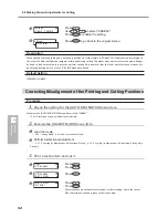
Cutting position and printing
position are misaligned.
Cutting position and printing
position are aligned.
Printing
position
Cutting
position
4.
Print and cut a test pattern for setting the correction values.
Press
.
Press
to execute.
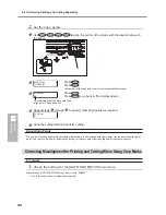
5.
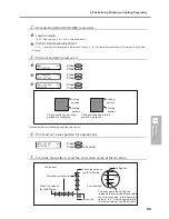
From the test pattern, read the value at the location.
6.
Enter the correction value you read.
Press
.
Press
.
Use
to set the correction value for [F] (the feed
direction).
Use
to set the correction value for [S] (the scanning
direction).
Press
to enable the setting.
Press
.
PRINT - CUT ADJ.
TEST PRINT 2
PRINT - CUT ADJ.
SETTING
F :- 0.30 - 0.30mm
S : 0.00 - 0.20mm
PRINT - CUT ADJ.
SETTING
Correction-value scale
Test pattern
Check the value on
the [SCAN] side.
Check the value on
the [FEED] side.
Cutting line
The point where the cutting line
intersects the correction-value scale
is the correction value. In this figure,
the value is "-0.3." Use the same
method to read the value on the
[FEED] side.
Cutting line
Scan direction
Summary of Contents for SP-300i
Page 1: ......
Page 2: ......
Page 24: ...22 ...
Page 25: ...23 1 Introduction Chapter 1 Introduction ...
Page 30: ...28 ...
Page 31: ...29 2 Operation Chapter 2 Operation ...
Page 50: ...48 ...
Page 51: ...49 3 Maintenance and Adjustment Chapter 3 Maintenance and Adjustment ...
Page 68: ...66 3 Maintenance and Adjustment ...
Page 69: ...67 4 Feature Reference Chapter 4 Feature Reference ...
Page 115: ...113 Chapter 5 What to Do If 5 What to Do If ...
Page 125: ...123 6 Specifications Chapter 6 Specifications ...
Page 133: ......
Page 134: ...R1 090619 ...


