9
SYB-5
advances to the FREQ Volume Check.
*
The DIRECT Volume Check and EFFECT Volume maximum value are detected
simultaneously. The DIRECT Volume Check is not run unless the EFFECT
Volume maximum is detected.
4. FREQ Volume Check
• Rotate the knob in the clockwise direction from minimum to center, then
to maximum; CHECK should change from lit to off to lit.
• When the maximum is detected, CHECK lights up, and then the process
advances to the RES Volume Check.
*
The FREQ Volume Check and DIRECT Volume maximum value are detected
simultaneously. The FREQ Volume Check is not run unless the DIRECT
Volume maximum is detected.
5. RES Volume Check
• Rotate the knob in the clockwise direction from minimum to center, then
to maximum; CHECK should change from lit to off to lit.
• When the maximum is detected, CHECK lights up, and then the process
advances to the DECAY/RATE Volume Check.
*
The RES Volume Check and FREQ Volume maximum value are detected
simultaneously. The RES Volume Check is not run unless the FREQ Volume
maximum is detected.
6. DECAY/RATE Volume Check
• Rotate the knob in the clockwise direction from minimum to center, then
to maximum; CHECK should change from lit to off to lit.
*
The DECAY/RATE Volume Check and RES Volume maximum value are
detected simultaneously. The DECAY/RATE Volume Check is not run unless
the RES Volume maximum is detected.
7. Expression Pedal (EV-5) Insertion Check
• Confirm that the MODE control is set to 2.
• With nothing connected to the EXP jack, confirm that CHECK is unlit.
• Connect the EV-5 to the EXP jack. Confirm that CHECK lights up.
8. Expression Pedal (EV-5) Volume Check
• Confirm that the MODE control is set to 3.
• Set the EV-5 pedal so that it is fully raised (minimum setting). Confirm
that CHECK lights up.
• Depress the EV-5 pedal so that it is completely pressed down (maximum
setting). Confirm that CHECK lights up. CHECK should be off with the
pedal between the minimum and maximum positions.
• Unplug the cable from the EXP jack to disconnect the EV-5. Confirm that
CHECK lights up.
*
Perform this check with the MINIMUM VOLUME on the side of the EV-5 set
to 0.
9. AF/AD Check
• Confirm that the MODE control is set to 4. CHECK goes out.
• Use the oscillator to input a sine wave at 200 Hz, -25 dBm (FLAT) to
INPUT.
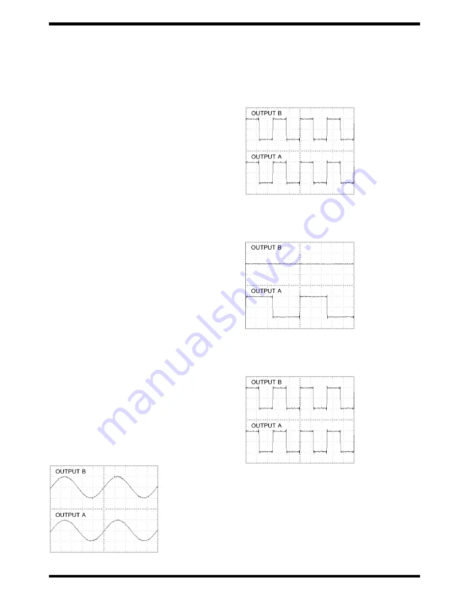
• Check the waveform output with the oscilloscope from both OUTPUT
A(MONO) and OUTPUT B. Confirm that the waveform is the same as
that shown in the figure and that there is no distortion.
fig.test-AFAD.eps_40
50mV/DIV, 1mS/DIV
• Check the waveform output with the noise meter from both OUTPUT
A(MONO) and OUTPUT B. Confirm that each waveform output is and
between -28.5 dBm and -25.5 dBm(FLAT).
10. DAC, JACK Switch Check
• Confirm that the MODE control is set to 5. CHECK lights up.
• Connect plugs to both the OUTPUT A(MONO) and OUTPUT B jacks,
and check the waveform output from both jacks with the oscilloscope.
Confirm that the waveform output from each is a 400-Hz rectangular
wave, with the waveform the same as that shown in the figure.
fig.test-DA400Hz.eps_40
50mV/DIV, 1mS/DIV
• Disconnect the plug connected to the OUTPUT B jack.
• Confirm that the waveform output from OUTPUT A(MONO) is a 200-Hz
rectangular wave, and that the waveform is the same as that shown in
the figure.
fig.test-DA200Hz.eps_40
50mV/DIV, 1mS/DIV
• Connect the plug to the OUTPUT B jack.
• Confirm that the waveform output from both OUTPUT A(MONO) and
OUTPUT B is a 400-Hz rectangular wave, with the waveform the same as
that shown in the figure.
fig.test-DA400Hz.eps_40
50mV/DIV, 1mS/DIV
11. DSP THRU MAXIMUM Output Check
• Confirm that the MODE control is set to 6. CHECK goes out.
• Use the oscillator to input a sine wave at 200 Hz, +5 dBm (FLAT) to
INPUT.
• Check the waveform output from both OUTPUT A(MONO) and
OUTPUT B with the oscilloscope. Confirm that the waveform is the same
as that shown in the figure and that there is no distortion.
Summary of Contents for syb-5
Page 12: ...12 Sep 2004 CIRCUIT BOARD fig board 1 fig board 2...
Page 13: ...13 SYB 5...


