4-22
4
8
9
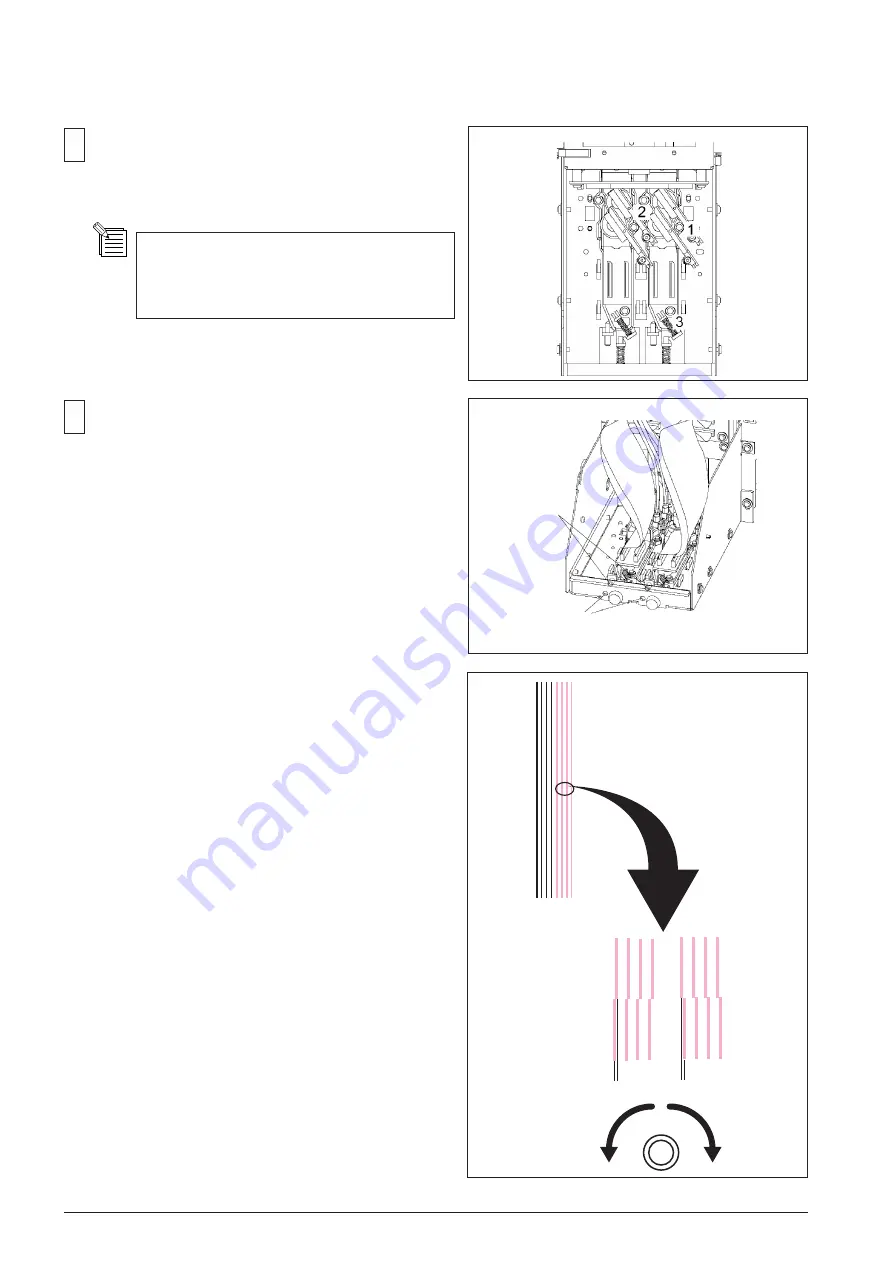
Loosen the 3 screws fixing the Head in order as shown
in the figure.
Adjustment
Screw
Hole for inserting
the Hexagonal
Wrench
Loosen the screws fixing the Head for 1/2 turn.
If the screws are loosened too much,
adjustments could not be performed correctly.
Insert the 1.5 mm Hexagonal Wrench to the hole of the
HEAD CARRIAGE, then, turn the screw so that the lines
of each color in the test pattern will be straight.
*Reference*
Position of the printing moves 1 line by turning
the screw 3/4 turn.
- When the upper lines are the left side of the lower
lines, turn the screw CW.
- When the upper lines are the right side of the lower
lines, turn the screw CCW.
Summary of Contents for VersaCamm SP-540V
Page 31: ...2 10 2 3 SERVO BOARD ...
Page 32: ...2 11 ...
Page 37: ...2 16 2 4 HEATER BOARD ...
Page 40: ...2 19 2 5 SUB BOARD ...
Page 88: ...3 43 9 Carry out the LINEAR ENCODER SETUP ...
Page 150: ...4 53 4 9 Check and make sure that the tension is within the range If not adjust it again ...


