4-4
CUTTING MENU
FORCE ADJUST
FORCE ADJUST
30gf
30gf
17 16
CUTTING MENU
CROPMARK SENSE
CROPMARK SENSE
OUTLEVEL CHECK
SERVICE MENU
CUTTING MENU
CROPMARK SENSE
ADJUST
ADJUST
+2 +1
FORCE ADJUST
200gf
200gf
56 57
CUTTING MENU
CROP-CUT ADJ.
CROP-CUT ADJ.
TEST PRINT
CROP-CUT ADJ.
SETTING
S:-0.40 -0.40mm
CROP-CUT ADJ.
TEST PRINT 2
PERFORMING
PERFORMING
CUTTING MENU
PRINT-CUT ADJ.
PRINT-CUT ADJ.
TEST PRINT
PRINT-CUT ADJ.
SETTING
PRINT-CUT ADJ.
TEST PRINT 2
PERFORMING
PERFORMING
MIN 0.7V MAX2.3
[2.0V ]
F:+0.30 +0.30mm
S:-0.40 -0.40mm
F:+0.30 +0.30mm
SERVICE MENU
SENSOR CHECK
FRSHODPULWwab
*** H *
1234
*EC
SERVICE MENU
THERMISTOR CHK
THERMISTOR CHK
HEAD:25 C/ 77 F
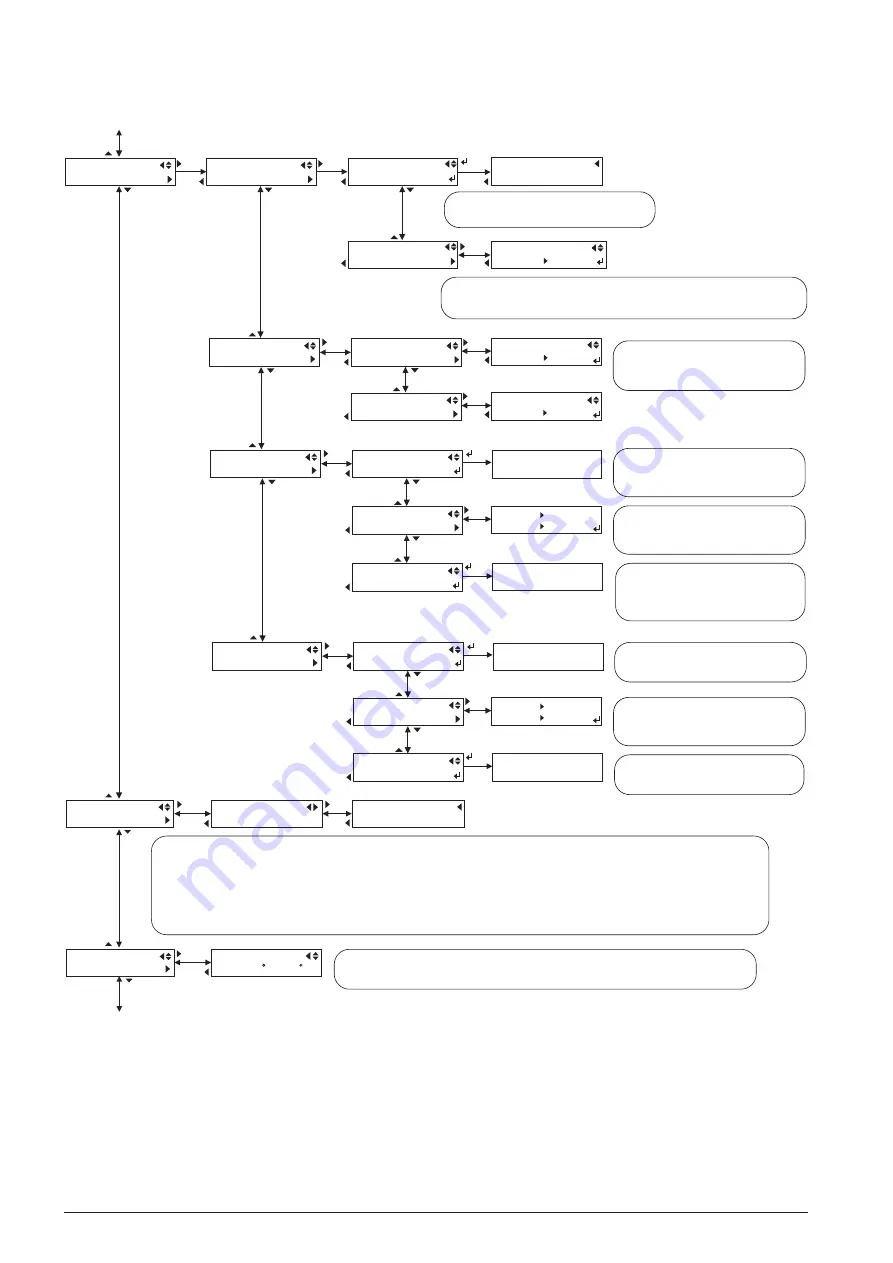
This is for adjusting the level of Crop Mark Sensor.
Refer to [4-8 CROP MARK SENSOR ADJUSTMENT].
This is for adjusting the Crop Mark Sensor sensitivity. There are 3 levels of sensitivity, 0, +1 and +2.
This adjustment may help when Crop Mark detection is failed with the default level setting.
Default: 0
TEST PRINT
TEST PRINT
Returns to menu with [MENU] key
TEST PRINT
TEST PRINT
Returns to menu with [MENU] key
This is for adjusting the Tool Pressure.
Refer to [4-13 TOOL PRESSURE ADJUSTMENT].
30gf Range: 0 to 30 Default: 17
200gf Range: 31 to 80 Default: 56
This test pattern is for adjusting the cut position
during automatic Crop Mark detection. It prints a
square Crop Mark and cuts the contour after
detecting the mark.
When it shows [ ], it means that it has never
been setup and it needs to be set. In this case, even
if adjustment is unnessesary due to the test result,
[0] must be set here.
This test pattern is for adjusting the cut position
during automatic Crop Mark detection. It prints a
square Crop Mark and continuously prints 0.1mm
scales for both scan and feed direction, and then
cuts crosswise after detecting the mark.
This test pattern is for adjusting the print & cut
position. It prints 3 square Crop Marks along the
scan direction and cuts the contours of the marks.
When it shows [ ], it means that it has never
been setup and it needs to be set. In this case, even
if adjustment is unnessesary due to the test result,
[0] must be set here.
This test pattern is for adjusting the print & cut
position. It prints 0.1mm scales for both scan and
feed direction and then cuts crosswise.
This menu displays the real-time status of each sensor. It shows [ ] when the sensor is ON.
The first page shows the status of each sensor. Each alphabet stands for as follows.
F: Front Paper Sensor
R: Rear Paper Sensor
S: Crop Mark Sensor
H: Head Lock Sensor
O: Limit Sensor
D: Side Cover Sensor
P: Maintenance Cover Sensor
U: Head Up/Down Sensor
L: Sheet Load Sensor
W: Pinch Roller Sensor
w: Wiper Sensor
a: TU Motor Drive Sensor
(When TU is connected)
b: Not in use
Head Up/Down Sensor (VP-300: Fixed)
H: Head HIGH
L: Head LOW
TU Motor Drive Sensor
: Driving
Blank: Not driving
The second page shows the status of each
Cartridge Sensor and Ink Empty Sensor.
Each color has 2 positions and the left side
on the display shows the left-side head.
Blank: Cartridge not inserted, Ink remains
C: Cartridge inserted, Ink remains
E: Cartridge not inserted, Ink empty
: Cartridge inserted, Ink empty
This is for checking Thermistor. It displays the temperature read from the thermistor placed on the board of the Head1.
The temperature on the left is in Celsius and the right is in Fahrenheit.
Since the temperature of the device possibly rises, it normally shows higher temperature than the room temperature.
*****
*****
*
*
*


