2-64
LEF2-300
2
Adjustment
Table Height Adjustment
2.
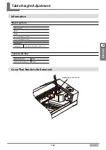
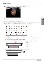
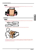
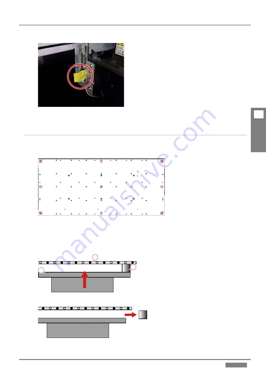
Tape the plate shown in the figure in the place to deauthorize the head gap sensor.
3.
Turn on the power switch and enter the service mode.
Measuring the distance at the five points of the print area
4.
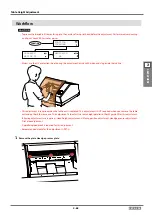
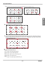
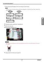
Measure the distance between the LM guide and the tabletop at the nine points of the print area.
Top view
4-1.
Move the table unit in feed direction by pressing the [
] [
] keys so that the front line of the print area is located under
the LM guide.
4-2.
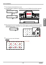
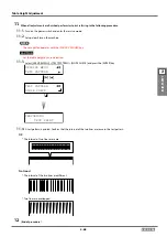
Select [SERVICE MENU] > [MOTOR MENU] > [AXIS MOVE] > [HEIGHT].
4-3.
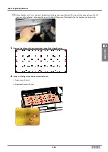
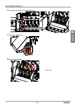
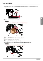
Set the block on the lower right corner of the print area, and move up the table by pressing the Z height keys.
1
3
2
1. Block
2. LM guide
3. Table
4-4.
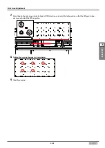
Move up the table until the block touches the LM guide, then remove the block.

